PHOENIX_SCANNER
Member
I have had a number of questions / comments about how to point a 800 mhz yagi in order to solve the "cut-outs" many scanner listeners get when monitoring the dreaded simulcast system.
Some feel that it should simply be pointed directly at the tower you want, and that this will yield the best results. The way a yagi is normally used (to achieve maximum gain to / from the target), that would be correct. But this solution is about ATTENUATION of the sites you don't want, not about GAIN on the site you do want.
Long story short, by using the field pattern of your antenna, and plotting your simulcast sites out, you will usually see that best signal ratio (between what you do want and what you don't want) will be achieved by pointing away from your "target" site, from a few, to 20 or so degrees depending, so that you still have a great signal from that site, but have attenuated as much as possible all the other sites. This is a balancing act, a compromise if you will.
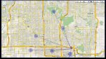
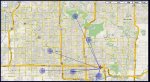
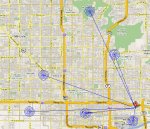
A fellow Arizona scanner enthusiast asked me to plot out his situation to suggest a polar angle for his antenna, so I did it for him to help him out, and am posting it here as an example. The first screen shot shows his approximate location (point "A"), and the simulcast sites around him. I have the advantage of using AutoCAD, which makes all of this quite easy, but it could be done just as well with pencil and straight edge, laid under the field pattern, and held up to a light. That would be one of many ways you could do the same thing. I am sure you can think of other methods. By using a compass and a printout when pointing your antenna, with a little patience you can get your yagi aimed for maximum impact.
This method works beyond the shadow of a doubt when tried, and it has been confirmed multiple times. I and others I know have went from hearing 25%-50% of what is being said, to more than 95%. With my new Pro-197 I am around 98%-99%, and often times get better reception than the Phoenix Police portables. Every day I hear them ask for a repeat when I heard every word loud and clear. The difference is night and day.
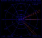
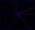
As you will see here in the second screen shot, for this gentleman the optimal angle is about 10 degrees counter-clockwise from the target, illustrating my point. In this case, the difference between pointing dead-on towards the site and 10 degrees off is not as huge as it is in my own case (third screen shot). In my case I have a little better scenario and I can get my two nearby offending towers down in the -35 db range. This gentleman will have to settle for a little worse ratio, because there are so many sites near him, and the two closest interfering sites are the two farthest apart on a polar grid, making things difficult. It should be noted that if the Northeast-most site uses a fairly short tower (it is on a police station), and has buildings blocking its view, it might work better to rotate the antenna a bit more clockwise, maybe 5 degrees more, for an offset of 5 degrees from target, ignoring the Northeast-most antenna, which would put his nearest offending tower into a more attenuated spot. It would be worth trying in this case, and comparing to the first suggested angle. Sadly, in this case you CAN'T ignore the Northern-most site, because it has the highest elevation of all the simulcast sites (atop a fairly tall mountain), and will have a clear shot at his antenna. So in any case the antenna is going to need some counter-clockwise offset from the target for optimal performance.
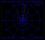
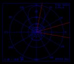
The third screen shot is my own situation. As you can see accurate pointing of my antenna really works out well in my location, yielding some really good attenuation. How well this method works for a given person depends on where he happens to lie between the towers. Some like myself, will benefit more than others. I can even imagine scenarios where it might not even help much, but that would be unlikely in most cases.
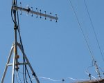
I used a Wilson 800 mhz yagi designed for cellular use in rural areas, an "N" to "SO-239" adaper, and a length of LMR-400 with PL-259's (sealed weather-tight). A quick google will easily locate these items, at around $100 total. Those wanting to really do it perfectly could spring for "N" connectors, but you will pay dearly for each one. Note that you need to insulate a metal mast if you want to ground it or use a non-metal mast to mount the yagi on, since mounting the antenna to a grounded mast means the whole mast and grounding assembly becomes part of the antenna. The whole beam is the element on this antenna in a sense. Keep this in mind. Wrapping the mast with a hefty dose of electrical tape did the trick for me. Also note that on the system being monitored here I DO activate the scanners own attenuation as well, further weakening the amount of signal getting through from the offending sites.
Since some new to the hobby will be considering this, and it might be their first antenna installation, I will add the following... For OUTDOOR antennas, I use a static discharge block where the line enters the house and ground it per NEC, or pretty close to it. That means multiple rods laid out correctly, and tied into the household / telecom grounding as well. I mention this because I think all antennas should be installed correctly to prevent damage to the front end of your valuable scanner. Air moving across the antenna or a nearby lightning strike can send a lot of energy down that line. You scanner might suffer a "deaf" front end, and still SEEM to be working correctly, though it will never again work like it did when new. It's a cruel fate that is easily avoided. Remember, this isn't "lightning protection". I say this because the typical 1000 foot bolt of lightning can be rated at around ONE BILLION VOLTS @ 40 kiloamperes, so don't expect anything to save your radio (or maybe other things like your home or your life either) if a bolt of lightning makes a direct strike on your antenna. I once had a test line run to play with a few radios when a big lightning storm came up. I unhooked the radio on that line and pointed it away from everything. As I laid in bed that night a nearby strike hit hard, and at that instant energy came down the unprotected line, and arced to the screw-on outer shield of the PL-259 at the end much like a spark plug would, lighting up the whole room. It made an impression I will not soon forget. Lightning is powerful stuff and can do amazing things, even when it doesn't directly touch something. Nuff' said.
I hope these screen shots answer some of the questions I have been getting. Good luck.
Some feel that it should simply be pointed directly at the tower you want, and that this will yield the best results. The way a yagi is normally used (to achieve maximum gain to / from the target), that would be correct. But this solution is about ATTENUATION of the sites you don't want, not about GAIN on the site you do want.
Long story short, by using the field pattern of your antenna, and plotting your simulcast sites out, you will usually see that best signal ratio (between what you do want and what you don't want) will be achieved by pointing away from your "target" site, from a few, to 20 or so degrees depending, so that you still have a great signal from that site, but have attenuated as much as possible all the other sites. This is a balancing act, a compromise if you will.
A fellow Arizona scanner enthusiast asked me to plot out his situation to suggest a polar angle for his antenna, so I did it for him to help him out, and am posting it here as an example. The first screen shot shows his approximate location (point "A"), and the simulcast sites around him. I have the advantage of using AutoCAD, which makes all of this quite easy, but it could be done just as well with pencil and straight edge, laid under the field pattern, and held up to a light. That would be one of many ways you could do the same thing. I am sure you can think of other methods. By using a compass and a printout when pointing your antenna, with a little patience you can get your yagi aimed for maximum impact.
This method works beyond the shadow of a doubt when tried, and it has been confirmed multiple times. I and others I know have went from hearing 25%-50% of what is being said, to more than 95%. With my new Pro-197 I am around 98%-99%, and often times get better reception than the Phoenix Police portables. Every day I hear them ask for a repeat when I heard every word loud and clear. The difference is night and day.
As you will see here in the second screen shot, for this gentleman the optimal angle is about 10 degrees counter-clockwise from the target, illustrating my point. In this case, the difference between pointing dead-on towards the site and 10 degrees off is not as huge as it is in my own case (third screen shot). In my case I have a little better scenario and I can get my two nearby offending towers down in the -35 db range. This gentleman will have to settle for a little worse ratio, because there are so many sites near him, and the two closest interfering sites are the two farthest apart on a polar grid, making things difficult. It should be noted that if the Northeast-most site uses a fairly short tower (it is on a police station), and has buildings blocking its view, it might work better to rotate the antenna a bit more clockwise, maybe 5 degrees more, for an offset of 5 degrees from target, ignoring the Northeast-most antenna, which would put his nearest offending tower into a more attenuated spot. It would be worth trying in this case, and comparing to the first suggested angle. Sadly, in this case you CAN'T ignore the Northern-most site, because it has the highest elevation of all the simulcast sites (atop a fairly tall mountain), and will have a clear shot at his antenna. So in any case the antenna is going to need some counter-clockwise offset from the target for optimal performance.
The third screen shot is my own situation. As you can see accurate pointing of my antenna really works out well in my location, yielding some really good attenuation. How well this method works for a given person depends on where he happens to lie between the towers. Some like myself, will benefit more than others. I can even imagine scenarios where it might not even help much, but that would be unlikely in most cases.
I used a Wilson 800 mhz yagi designed for cellular use in rural areas, an "N" to "SO-239" adaper, and a length of LMR-400 with PL-259's (sealed weather-tight). A quick google will easily locate these items, at around $100 total. Those wanting to really do it perfectly could spring for "N" connectors, but you will pay dearly for each one. Note that you need to insulate a metal mast if you want to ground it or use a non-metal mast to mount the yagi on, since mounting the antenna to a grounded mast means the whole mast and grounding assembly becomes part of the antenna. The whole beam is the element on this antenna in a sense. Keep this in mind. Wrapping the mast with a hefty dose of electrical tape did the trick for me. Also note that on the system being monitored here I DO activate the scanners own attenuation as well, further weakening the amount of signal getting through from the offending sites.
Since some new to the hobby will be considering this, and it might be their first antenna installation, I will add the following... For OUTDOOR antennas, I use a static discharge block where the line enters the house and ground it per NEC, or pretty close to it. That means multiple rods laid out correctly, and tied into the household / telecom grounding as well. I mention this because I think all antennas should be installed correctly to prevent damage to the front end of your valuable scanner. Air moving across the antenna or a nearby lightning strike can send a lot of energy down that line. You scanner might suffer a "deaf" front end, and still SEEM to be working correctly, though it will never again work like it did when new. It's a cruel fate that is easily avoided. Remember, this isn't "lightning protection". I say this because the typical 1000 foot bolt of lightning can be rated at around ONE BILLION VOLTS @ 40 kiloamperes, so don't expect anything to save your radio (or maybe other things like your home or your life either) if a bolt of lightning makes a direct strike on your antenna. I once had a test line run to play with a few radios when a big lightning storm came up. I unhooked the radio on that line and pointed it away from everything. As I laid in bed that night a nearby strike hit hard, and at that instant energy came down the unprotected line, and arced to the screw-on outer shield of the PL-259 at the end much like a spark plug would, lighting up the whole room. It made an impression I will not soon forget. Lightning is powerful stuff and can do amazing things, even when it doesn't directly touch something. Nuff' said.
I hope these screen shots answer some of the questions I have been getting. Good luck.
Attachments
Last edited: