Replacing internal lithium battery on AOR 3000A

Status
Not open for further replies.

All-Modes

Member
Joined
Feb 14, 2015
Messages
7
Location
London, England
Greetings.....

I'm having problems replacing the internal lithium battery in my AOR3000A.

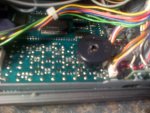
I've removed the two-piece circular black plastic cover with a hole in its top-side which (I think...) holds the battery against two metal prongs soldered to the PCB behind the board holding the operating buttons for the receiver.

The "prongs" go through two holes at the bottom of the circular plastic holder - resting against the bottom of the CR 2032 battery - which can be removed by separating the two halves of the plastic holder.

My problem is that I thought the two metal "prongs" needed to be soldered to the battery - but there are no signs this was done in the case of the existing battery - I also can't see how this could be done.

(The scanner's memory was fine (and the battery working) until I left it unplugged and stored in a cupboad for a couple of years - after which the receiver would not power-up)

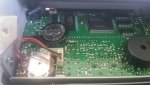
Now, assuming I have indeed removed the battery cover and not some other component, how do I re-attach the two-part plastic battery cover (with the new battery inserted) back onto the PCB? It was hard to pull-off the board and will some-how to be stuck back-on the PCB. Usng tape? Glue?

I've a horrible feeling I might have removed the wrong component....if so, what is the two-piece black plastic "holder" for?

Could someone please give me step-by-step instructoins for replacing the internal battery - including giving confirmation of where it is located on the PCB?

I've read earlier Forum postings on eplacing the battery - but am stil confused.

I'd also like to know - one way or the other - if the two-part black plastic "container" I've removed is the battery holder.

Hope this garbled account makes some kind of sense - I can't undrstand why AOR have made replacing a battery with a finite life so hard....and why the receiver handbook handbook doesn't make clear hiw to do it..

Any help/advice gratefully received.

Many thanks.

All Modes (Pete)
 

dkf435

Member
Joined
Apr 15, 2006
Messages
729
Location
Sweet Home/Foster OR
Need a picture, all my AR3000/A radios had a battery with just heat shrink around the rim and spot welded tabs. Replaced them with a computer coin cell holder with leads and double stick taped to a place inside radio.

David Kb7uns
 

All-Modes

Member
Joined
Feb 14, 2015
Messages
7
Location
London, England
Pic of battery cover on PCB on my AOR3000A

Thanks for the helpful reply, David (dkf 435). Any further help would be appreciated - I'm out-of-my-depth. .

Here's a pic of the black plastic cover for the internal battery on my AOR 3000A. It is mounted on two metal "prongs/tags" connected to the PCB immediately behind the key-pad (right-hand side behind the mem bank button.)

The holder is as described in my first posting for this thread (in two halves - bottom half containing CR2032 coin battery with the two "prongs" making contact with (but not soldered to) the battery via two holes. the top part of the holder is detachable to insert the battery).

I'm in the UK where the AOR was bought second-hand - so I don;t know if this battery fitting is standard to the UK or was added by a previous owner.

An electronics shoP in the UK called Maplins stocks a "CR2032 lithium battery box with a 20mm pin spacing for a PCB-mounting". A photo can be seen on the Maplins website by Googling Maplins lithium battery box code L01AC.

Would this be suitable for the AOR3000A?

Thank you again.

Pete

PS: Has any Forum membver come across a bttery holder similar to the one in the photo?
 

Attachments

  • IMG-20150216-00741.jpg
    IMG-20150216-00741.jpg
    163.8 KB · Views: 1,969

dkf435

Member
Joined
Apr 15, 2006
Messages
729
Location
Sweet Home/Foster OR
I was afraid that was what you were describing. THAT IS NOT A BATTERY it is the piezo electric buzzer for the key beep.

The cpu backup battery is usually to the left in the picture over next to the rotary tunning control, it usually has a square of the black fabric electrical tape on it.

When removing the battery from the board I usually remove the face, must remove knobs and take screws going through plastic tabs into the metal frame.

David Kb7uns

Picture with tape removed

Also note top left of picture there is a baud rate switch and a cpu reset button.
 

Attachments

  • ar3kbattery.jpg
    ar3kbattery.jpg
    46.8 KB · Views: 2,785

All-Modes

Member
Joined
Feb 14, 2015
Messages
7
Location
London, England
Thanks for clearing up the buzzer/bleep mix-up, David.

Will the radio still work as a scanning receiver with the buzzer ripped out? (Minus the bleep, of course?) Also, how do I re-attach it to the PCB? Do I just re-fit the bottom half of the buzzer housing onto the two metal prongs wired to the PCB, replace the metal disc (which I mistook for the coin battery) and slot back on the rubber "top" of the buzzer?

I never used the keyboard bleep function, so won't miss it if replacing the buzzer proves impossible.


And, at least, I haven't (so far) destroyed the battery box.

Can you please give step-by-step instructions for replacing the battery once I''ve taken off the black fabric tape covering it?

What do I need to unsolder and re-solder? I couldn't follow your references to "remove the face, must remove knobs and take screws going through plastic tabs into the metal frame."


What knobs? Which screws? How is the battery holder wired to the PCB?

As someone who confused a buzzer with a battery holder, I need the battery replacement proceedure explained one step at a time.

Your patience is appreciated.

Thanks again for bearing with me.

Pete
 

dkf435

Member
Joined
Apr 15, 2006
Messages
729
Location
Sweet Home/Foster OR
The battery has the metal legs spot welded to it. You may be able to find an exact replacement but I just get a coin cell holder and solder wires to holder, heat shrink wires to holder and then wrap or heat shrink entire assembly for remote mounting in radio.

You will need to remove bottom and then top covers remember to un hook speaker wire.

Remove the knobs and power switch button.

Remove the four screws that hold plastic front face to the metal frame 2 on each side of face plate.

Remove the plastic grid spacer from between the key switches.

There will be two pads below the lower edge of the LCD screen with the negative one to the upper left of the down button and the positive one to the upper left of the up button. You will need some fine solder and possibly some flux to reflow the solder on the battery pins so the battery may be removed and then the traces and thru plated holes cleaned out of solder. If you cannot solder or desolder well it is best to find someone that can as the traces are fragile and if lifted or damaged are extremely hard to repair.

Insert the leads from the battery into the correct polarity holes and resolder and resecure / insulate the battery.

Replace keypad spacer, only fits one way, notches cut for wires on board surface.

Replace front face and center on screw holes and tighten lightly so you do not crack plastic.

Replace knobs and button with notches in correct positions.

Replace top cover.

Hook up speaker wire.

Hook up power connector and turn radio on, may have to cycle power switch and reset button on CPU board until radio boots up, will usually come on and show 80.0000 MHz and WFM.

Once radio boots up replace bottom cover.


Memory battery is only used if radio is disconnected from power source so sometimes these batteries will last a very long time, if you keep radio in box then it is a lot shorter life.

David Kb7uns
 

All-Modes

Member
Joined
Feb 14, 2015
Messages
7
Location
London, England
Thanks for another very helpful reply, David (dkf435). Most of my soldering has been restoring and building valve radios - so I may have to pay a professional to replace the battery. But at least I can now locate the battery - which is useful progress.

Will the radio still work as a receiver without the piezo electric buzzer for the key beep in place? I don't require a bleep function - and would gladly settle for buzzer housing not being re-fitted.

But how would I do a re-fit if the buzzer needs be re-connected for the rest oif the radio to work?

The two thin metal prongs which connected the buzzer to the PCB are still in place, but I can't see how to reconnect these to the bottom half of the rubber/plastic buzzer housing.

Are the prongs just pushed through the two holes in the bottom half of the buzzer-housing to make contact with its (detachable) circular metal disc? And does the housing top half (with a hole in the top) just make a push-fit with the bottom half?

If so, what attaches the housing to the PCB and keeps it in place to activate the bleep?

Again, any buzzer-related help woujld be much appreciated.

Many thanks.

Pete
 

All-Modes

Member
Joined
Feb 14, 2015
Messages
7
Location
London, England
Will the AOR3000A work without a bleep buzzer fitted?

Thanks for the links, David - but is it necessary to have the "buzzer" wired to the PCB for the radio to work as a receiver? (Once a new battery has been fitted and reset carried out)

Will the AOR3000A function (albeit without bleeps) with no buzzer fitted? Or rather, if I don't attempt a re-fit after tearing it off the PCB having mistaken it for a battery cover.

Easily done.....

I can monitor and scan frequencies quite happily without the distraction of bleeps...

Pete
 

dkf435

Member
Joined
Apr 15, 2006
Messages
729
Location
Sweet Home/Foster OR
Some times it is nice to know if the key is being pressed but otherwise it is not needed.

I have a spare board laying around incase one fails or I want to upgrade my AR3000 up to an A model.

David Kb7uns
 

All-Modes

Member
Joined
Feb 14, 2015
Messages
7
Location
London, England
Thanks again, David.

A final question: how do I fix a new buzzer-housing to the PCB?

At present - with the exsiting buzzer removed from the PCB - two thin metal conecting strips about half an inch long which used to connect to the buzzer via two holes in the bottom of its housing remain soldered to the board, but not connected to anything.

Will the new buzzer housing be in two halves (like the existing one)- with a means of conecting the tag-strips from the board to the bottom half of the buzzer housing?

And will there be a couple of solder-tags in the buzzer housing to make the contact to the board via the two strips of metal soldered to it?

Thanks again for your expertise and patience.... I think we are nearly there....

Pete
 

dkf435

Member
Joined
Apr 15, 2006
Messages
729
Location
Sweet Home/Foster OR
You will need to solder the two pins of the transducer into the holes on the PCB, if you are having trouble figuring this out you really need to find someone that has the skills to do this work.
 
Status
Not open for further replies.
Top