
- Forums
- Scanners, Receivers and Related Equipment Forums
- Antennas and Associated Hardware
- Build Your Own Antenna
You are using an out of date browser. It may not display this or other websites correctly.
You should upgrade or use an alternative browser.
You should upgrade or use an alternative browser.
My new homemade LPDA (and the first)
- Thread starter red-dog
- Start date
- Status
- Not open for further replies.
N5TWB
Member
Looks cool, now bring the details: materials, construction, performance, who are you so interested in that it made you build this?
prcguy
Member
I don't think that will work the way you made it. That's a split boom design where the boom is the feedline and every other set of elements need to reverse phase. It appears you have all elements on one boom pointing up and all elements on the other boom pointing down and you need to reverse every other set of elements.
Starting at the back or longest elements, if the boom facing you in the picture has an element going up, then the next shortest element will point down and the next smallest will point up, etc. The boom facing away from you would start with the longest element pointing down and the next shortest pointing up, etc.
The way its put together now is just a large nest of dipoles with no directionality.
prcguy
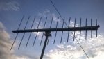
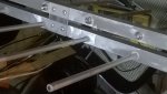
This is my new LPDA homemade antenna for UHF-AIR (225-400 MHz) The design was taken from an old magazine and recalculated for the frequencies of interest.
My Log-periodic Yagi
PRCGUY is correct. See the pictures of my 2 meter LPY as examples. Also, if the aluminum boom and/or elements are anodized you must remove it from element and feed-line contact points for maximum conductivity.
PRCGUY is correct. See the pictures of my 2 meter LPY as examples. Also, if the aluminum boom and/or elements are anodized you must remove it from element and feed-line contact points for maximum conductivity.
Last edited:
more images LPDA 225-400 MHz
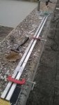
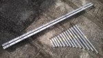
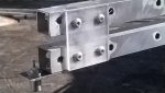
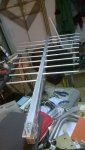
I'm posting more photos to give a better idea of the construction of this system LPDA. The elements are aluminum Ø8 mm and the two boom are 20 mm with a length of 1.50 m.
I'm posting more photos to give a better idea of the construction of this system LPDA. The elements are aluminum Ø8 mm and the two boom are 20 mm with a length of 1.50 m.
Attachments
prcguy
Member
That is very nice construction and a beautiful looking antenna, however it will not function the way you made it. Look at the pictures posted by rivardj that shows how the elements should be arranged.
red-dog has all the elements on one boom facing the same direction and instead, every other element must point the opposite direction. Please read the other posts describing this, otherwise the antenna will not work as a Log Periodic and will be nothing more than random bits of aluminum in the sky.
I understand there may be a language problem understanding my description but please look up some pictures of other Log Periodic antennas on the Internet to see what we are discussing.
prcguy
I'm posting more photos to give a better idea of the construction of this system LPDA. The elements are aluminum Ø8 mm and the two boom are 20 mm with a length of 1.50 m.

prcguy
Member
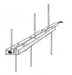
The picture you posted is the correct way to arrange the elements and does not match what you built.
Looking at the left side boom in the picture the element closest to the viewer points up and the matching element on the right side boom points down. Looking at the next set of elements away from the viewer, the left boom element now points down and the right boom element points up. The last set of elements the farthest away from the viewer where the coax exits the left boom element points up again and the right boom points down.
If you look at your completed antenna with the same view, all the elements on the left boom point up and all the elements on the right boom point down, they do not reverse like the picture you posted.
Looking at your construction it should be easy to take some the antenna apart and arrange the elements to match the picture.
prcguy
This is perhaps clearest example
Looks cool but what are you using for numbers (spacing and length)? I agree with prcguy you have to change the elements they all can't be up on one boom and down on the other. You have to change the arrangement one up one down and it opposes the other boom one down one up.
prcguy
Member
It would be interesting to test the antenna as you built it then test again after its fixed. Please let us know how it works.
prcguy
prcguy
I have done a mistake by 'stupid', has been the rush to mount the antenna or old age? Thanks for the advice, today I will to move items !!!!!
reconrider8
Member
where did you get the square aluminum tubing and the element materials? i would love to try this as a first antenna
Order Aluminum Square Tube Alloys 6061, 6063 in Small Quantities at OnlineMetals.com
Online metals has the best selection and prices for square tubing for booms, for the elements I use dx engineering.
DX Engineering Aluminum Tubing - Free Shipping on Orders Over $99 at DX Engineering
Online metals has the best selection and prices for square tubing for booms, for the elements I use dx engineering.
DX Engineering Aluminum Tubing - Free Shipping on Orders Over $99 at DX Engineering
The error has been corrected, now LPDA this should work. . . was fixed to the mast, and is fed with 75 ohm cable TV, the connector is an 'F'
├┼┼┼│
ALUMINIUM BOOM - mm. The 20x20 mm. 1500
ELEMENTS OF ALUMINUM TUBE Ø 8
I'm sorry but I do not have proper equipment to be able to give more technical information, is the only tool. . . the scanner, I will hear something in the next few days.
├┼┼┼│
ALUMINIUM BOOM - mm. The 20x20 mm. 1500
ELEMENTS OF ALUMINUM TUBE Ø 8
I'm sorry but I do not have proper equipment to be able to give more technical information, is the only tool. . . the scanner, I will hear something in the next few days.
I have no doubts you will hear something, please tell us bands where you notice improved activity,(vhf/uhf/400/800/900) also try to point the antenna toward your city or area of interest. Please if you could post the dimensions of the reflectors and how far apart they are along the boom.
majoco
Stirrer
- Status
- Not open for further replies.
Similar threads
- Replies
- 3
- Views
- 466
- Replies
- 22
- Views
- 968
- Replies
- 7
- Views
- 578
- Question
BCD436HP/BCD536HP:
BCD536HP connecting external antenna cuts out audio output
- Replies
- 17
- Views
- 842