I did some research on solutions others have done to get a fixed output audio level on the PSR-600. I got some good ideas and then came up with my own solution after a review of the schematic for the scanner.
I had the following goals:
1) Fixed audio output level that was independent of the volume knob.
2) Audio that was "leveled" based on FM vs NFM (I made an interesting find below...)
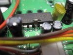
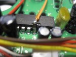
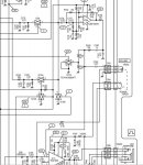
I reviewed the schematic for the Pro-197 (available from Radio Shack) and found an easy to access point at which the level is independent of the volume knob and also takes in to account the level differences between wideband FM and narrowband FM. This point is located on IC11, pin 5.
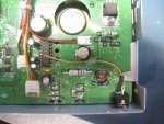
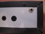
I used a 1206 sized surface mount cap and stood it up on IC11 pin 5 and ran a wire to a 1/8" headphone jack that I installed on the back panel. I was careful to installed the jack in such a way that it sits flush on the PCB (so that the jack doesn't move around - as they often like to do). I ran a wire from the top of the 0.01uF cap over to the tip connection on the 1/8" jack.
Pictures attached.
Other articles I found talked about tapping into the volume knob wiring or tapping off of IC8 pin 1. While those locations have a level independent of the volume knob, they don't take into account audio leveling that's done for FM vs NFM. So that's what started the hunt for my solution (detailed above).
Interesting note... I ran tests with a signal generator and changing the deviation of a 1 kHz tone along with toggling the FM vs NFM setting on the scanner. I found that FM vs NFM has no impact on the amount of audio gain. The change in audio level comes from changing the Audio Boost setting in the Expert section of the menu. I don't quite understand why GRE did this...
Here's some data with Audio Boost off:
165 MHz signal at -100 dBm using 3.0 kHz deviation results in ~0.35 vpp on IC11 pin 5. This voltage is the same for FM or NFM mode settings.
165 MHz signal at -100 dBm using 1.5 kHz deviation results in ~0.20 vpp on IC11 pin 5. This voltage is the same for FM or NFM mode settings.
When you turn on Audio Boost:
165 MHz signal at -100 dBm using 3.0 kHz deviation results in ~0.61 vpp on IC11 pin 5. This voltage is the same for FM or NFM mode settings.
165 MHz signal at -100 dBm using 1.5 kHz deviation results in ~0.34 vpp on IC11 pin 5. This voltage is the same for FM or NFM mode settings.
Note I also measured at the speaker terminals and saw similar numbers.
Conclusion:
To get the same level of audio for a NFM signal, you need to turn Audio Boost ON.
Maybe this is covered in the manual or elsewhere on this forum...but I thought it was an interesting discovery.
Hope this mod helps some others on the forum!
I had the following goals:
1) Fixed audio output level that was independent of the volume knob.
2) Audio that was "leveled" based on FM vs NFM (I made an interesting find below...)
I reviewed the schematic for the Pro-197 (available from Radio Shack) and found an easy to access point at which the level is independent of the volume knob and also takes in to account the level differences between wideband FM and narrowband FM. This point is located on IC11, pin 5.
I used a 1206 sized surface mount cap and stood it up on IC11 pin 5 and ran a wire to a 1/8" headphone jack that I installed on the back panel. I was careful to installed the jack in such a way that it sits flush on the PCB (so that the jack doesn't move around - as they often like to do). I ran a wire from the top of the 0.01uF cap over to the tip connection on the 1/8" jack.
Pictures attached.
Other articles I found talked about tapping into the volume knob wiring or tapping off of IC8 pin 1. While those locations have a level independent of the volume knob, they don't take into account audio leveling that's done for FM vs NFM. So that's what started the hunt for my solution (detailed above).
Interesting note... I ran tests with a signal generator and changing the deviation of a 1 kHz tone along with toggling the FM vs NFM setting on the scanner. I found that FM vs NFM has no impact on the amount of audio gain. The change in audio level comes from changing the Audio Boost setting in the Expert section of the menu. I don't quite understand why GRE did this...
Here's some data with Audio Boost off:
165 MHz signal at -100 dBm using 3.0 kHz deviation results in ~0.35 vpp on IC11 pin 5. This voltage is the same for FM or NFM mode settings.
165 MHz signal at -100 dBm using 1.5 kHz deviation results in ~0.20 vpp on IC11 pin 5. This voltage is the same for FM or NFM mode settings.
When you turn on Audio Boost:
165 MHz signal at -100 dBm using 3.0 kHz deviation results in ~0.61 vpp on IC11 pin 5. This voltage is the same for FM or NFM mode settings.
165 MHz signal at -100 dBm using 1.5 kHz deviation results in ~0.34 vpp on IC11 pin 5. This voltage is the same for FM or NFM mode settings.
Note I also measured at the speaker terminals and saw similar numbers.
Conclusion:
To get the same level of audio for a NFM signal, you need to turn Audio Boost ON.
Maybe this is covered in the manual or elsewhere on this forum...but I thought it was an interesting discovery.
Hope this mod helps some others on the forum!