• To anyone looking to acquire commercial radio programming software:

    Please do not make requests for copies of radio programming software which is sold (or was sold) by the manufacturer for any monetary value. All requests will be deleted and a forum infraction issued. Making a request such as this is attempting to engage in software piracy and this forum cannot be involved or associated with this activity. The same goes for any private transaction via Private Message. Even if you attempt to engage in this activity in PM's we will still enforce the forum rules. Your PM's are not private and the administration has the right to read them if there's a hint to criminal activity.

    If you are having trouble legally obtaining software please state so. We do not want any hurt feelings when your vague post is mistaken for a free request. It is YOUR responsibility to properly word your request.

    To obtain Motorola software see the Sticky in the Motorola forum.

    The various other vendors often permit their dealers to sell the software online (i.e., Kenwood). Please use Google or some other search engine to find a dealer that sells the software. Typically each series or individual radio requires its own software package. Often the Kenwood software is less than $100 so don't be a cheapskate; just purchase it.

    For M/A Com/Harris/GE, etc: there are two software packages that program all current and past radios. One package is for conventional programming and the other for trunked programming. The trunked package is in upwards of $2,500. The conventional package is more reasonable though is still several hundred dollars. The benefit is you do not need multiple versions for each radio (unlike Motorola).

    This is a large and very visible forum. We cannot jeopardize the ability to provide the RadioReference services by allowing this activity to occur. Please respect this.

Icom F5011/F6011 Repeater Connection Modification

Status
Not open for further replies.

KF7SIF

Member
Joined
Nov 28, 2011
Messages
7
A few years ago, I remember seeing an instruction sheet on the Internet for connecting two Icom F5011/F6011 mobile transceivers together for creating a simple repeater. The repeater setup lacked a controller and didn't have support for full duty cycle, but it would still be good for instruction and demonstration. I've looked all over the Internet and can't seem to find this instruction. Does anyone still have a copy of it?
 

70cutlass442

Member
Premium Subscriber
Joined
Jan 24, 2010
Messages
404
Here is info the ICOM sent me earlier this year regarding hooking a 5061/6061 radio to a FR5000 repeater to be used as a link radio... I later on verified with ICOM that the 5011/6011 was the same and they assured me the same modification worked on both (see replies below)

"Hi Jon,
Please see the attached app note that shows linking a F5061/6061 radio to FR5000/6000 repeater.
I am also sending you the pin out for DB-25 connector for the F5061/6061 radio and F5011/6011 option cable."

"Greetings,

You should be able to the F6011 radio but we have not used it here and that's i do not have an app note for that.

F6011 and F6021 pin out and solder beads are same as it shows in the pinout i sent you earlier."

I attached all of the info that he sent me which gives you more than enough info to complete your project.
 

Attachments

  • OPC-2078_1939 pinouts.pdf
    248.9 KB · Views: 1,558
  • F5061_F6061 DB25 pin assignment and Cut Points.pdf
    118.7 KB · Views: 575
  • F5061 F6061 DB-25 Input Modulation.pdf
    197.3 KB · Views: 561
  • FR5000 Series to F5061D Series Link Radio.pdf
    23.5 KB · Views: 475

KF7SIF

Member
Joined
Nov 28, 2011
Messages
7
Thx: Re: Discussion on 6011 Repeater

This is great and gets me most of the way there. From what I understand from what you sent so far, besides the cross-connect cable, the only thing needed for a 6011/6011 demo repeater would be to connect Bead N. I don't have the board layout diagram for identifying Bead N's location. Could you please send it to me. That should complete things. Thanks again!!!

- KF7SIF now W7TBW (except for here).
 

KF7SIF

Member
Joined
Nov 28, 2011
Messages
7
hread: Icom F5011/F6011 Repeater Connection Modification Reply to Thread

OK, so I guess I'm really tired or just too dumb to see it. It's not clear to me which radio in a 5061/5061 repeater pair would get the Solder N connection, i.e. is that for the the transmit or the receive element. Could you also send me the "Program Radio" settings for each device the Rx and the Tx. Obviously, they're going to be different from each other but I was never good at keeping the polarity of handshaking signals separate. Thanks again.

- tw (KF7SIF now W7TBW).
 

KF7SIF

Member
Joined
Nov 28, 2011
Messages
7
Thread: Icom F5011/F6011 Repeater Connection Modification Reply to Thread

I guess I was tired. From the FR5000 Series to F5061 link app, it looks like the F5061 radio is acting like the transmit side and gets the N solder connection. If this is the case and the F5061/F5011 can work both ways, the receive side could be another F5061 instead of an FR5000.

What this doesn't tell me though is which radio is going to have external audio active, or whether it doesn't matter. If it doesn't matter, then I really only need to connect up one external speaker to one unit for local monitoring of the test repeater setup, and it shouldn't matter which unit I use. Apparently, the other speaker would then be bypassed using an input jack to an open line to prevent having competing chatter from two separate speakers. I would like to get some confirmation on this, though.

The "program radio" settings seem to be the same for both sides with the possible exception of the EPTT. In the app, the FR5000 "program radio" settings show the input EPTT on pin 18 as being active low. No similar comment is made for the F5061. Does this mean it doesn't matter or should I be setting EPTT low on the F5061, i.e. F5011, as well.

Unless the motherboard is marked so that each coffee bean is labeled, I will still need a board layout diagram to identify the "N" coffee bean. Thanks again.

W7TBW
 

KF7SIF

Member
Joined
Nov 28, 2011
Messages
7
Thread: Icom F5011/F6011 Repeater Connection Modification Reply to Thread

One last question. Nothing is shown here about diabling the Rx on the Tx radio or the Tx on the Rx radio. The connections are symmetrical and reversed. Does this mean this is a dual or full duplex repeater if a pair of non-competing duplex frequencies are used, or does this mean the non-used Rx on the Tx side and the non-used Tx on the Rx side have to be disabled somehow?
 

jeepsandradios

Member
Feed Provider
Joined
Jul 29, 2012
Messages
2,065
Location
East of the Mississippi
I have built many of these with the F121/221 and the 5011/6011 radios. As for the TX RX I normally just program the radio with the same frequency on TX/RX per radio (IE: RX RADIO 458.xxx RX and 458.xxx tx / TX RADIO 453.xxx RX and 453.xxx TX) Normally I will use a off the wall PL or DPL on the rx/tx channel not in use (RX repeater radio TX tone different than used, same on transmit radio). That way if Im on TA I wouldn't bring up the repeater completely backwards.

These work very well as limited use repeaters. ICOM actually sold a basic model repeater (Think it was the CY series) with this concept.
 

70cutlass442

Member
Premium Subscriber
Joined
Jan 24, 2010
Messages
404
Well, I haven't implemented this design yet... But I do have have an FR4000 hooked to a F221 as a link radio. My setup however requires the link radio be cable of TX and RX so I utilized the EPTT in and out on both radios. I am not 100% sure which bead you will need to solder on but it is easy enough to try one and do the other if need be. Also, the board was infact labeled on the 221 I did so I would assume the 50/60 series is as well. The FR5000 sales handbook has the programming settings and board layout on page 72/73... but the file appears to large to attach (11.1MB) If you can locate that document, that will give you more info on what you are trying to do.
 

KF7SIF

Member
Joined
Nov 28, 2011
Messages
7
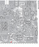
OK, so as a sanity check I contacted Icom just to confirm everything so as to make things as easy as possible by avoiding making unnecessary or incorrect changes. Their response follows my query. They sent me the same files on "DB-25 Pin 8 Input Modulation Connection Change in F5061/F6061 Radios" and "F5021/F5121/5011 Series Radios 25 or 15-Pin Connector Signals (OPC-2078 or OPC-1939)" that I had received before from the forum, but they had one new piece of information that contradicts what everyone has been saying about Coffee Bean N, as it applies specifically to F6011/F6021 radios. They also sent me a partial board layout diagram, which I've attached, for the F6061 radio that shows the location of Coffee Bean N, as well as some of the other connect points. Here's what they had to say about Coffee Bean N:

Customer By CSS Web (TIMOTHY WHITMORE) (05/06/2016 10:54 AM)

Hello,

Could I get the Board Layout Diagram for the F6011/F6021. I have a mod from Icom that states that it is the same as the F6121 or the F6061. What I need to do is to identify the location of Coffee Bean N so that I can perform the Pin 8 Input Modulation Connection Change in F5061/F6061 per the 6 Jan. 2010 application note. I have the Technical Update Bulletin from 14 July 2015 that shows the location of Coffee Bean T, but that doesn't apply to my older model. I still need to know where Coffee Bean N is.


Subject: Board Layout Diagram for the F6011/F6021

Response By Email (Harry) (05/06/2016 11:04 AM)

Greetings,

The IC-F6011/F6021 does not need the N bead modification done on the radio. Attached is the option cable pin out for it.

I am also sending you the jpeg that shows the N bead location on the main board of F5061/6061...
The complete board layouts are only in the Service manual that are only available to authorized Icom Dealers. You can get one by contacting one of the local Dealers near you.

Click here for information regarding Warranty Registration, Service/Repair Authorization form, Knowledge Base & Technical Support: Support - Icom America

Sincerely,
Harry
Technical Support Representative
Icom America, Inc.
12421 Willows Road NE
Kirkland, WA 98034
_
 

Attachments

  • N Bead.jpg
    N Bead.jpg
    123.8 KB · Views: 1,034

VE2MBT

Newbie
Joined
Jan 17, 2017
Messages
1
Icom Repeater

For as long as Icom have the IC-5011/6011 séries, i use them as repeater / link or crossband repeater with great succes. i run radio 5w for link or crossband repeat and 5w with external PA for repeater
 

Attachments

  • répéteur.jpg
    répéteur.jpg
    59.9 KB · Views: 773
Status
Not open for further replies.
Top