
You are using an out of date browser. It may not display this or other websites correctly.
You should upgrade or use an alternative browser.
You should upgrade or use an alternative browser.
Programming Cable Pinout?
- Thread starter ausscan
- Start date
- Status
- Not open for further replies.
DickH
Member
- Joined
- Mar 12, 2004
- Messages
- 4,067
Does anyone have the pin out/circuit diagram for the cable to program a PRO-97?
The pin-out is not going to help you without the circuit diagram and parts list of all the components built into the cable. You'll probably have to bite the bullet and buy one.
Funny thing, for whatever reason the later scanners (PSR-300, PSR-400, PRO-164, PRO-163) require the stereo connector and USB type cable. I have not been able to get the old COM cable to work with the newer scanners.Will this circuit work with the pro 163 also???
Perhaps someone else out there like Don S can chime in on this issue.
Evert
Member
I think the scanners newer than the Pro-97 use full duplex mode which has the computer send TX signal to the tip and use the Ring for the RX signal . Thus they require use of a TRS (“stereo”") plug.
plug.
plug.
Last edited:
Evert
Member
Is it possible if we forget the USB conversion can't we then still use the com port rs232?? TX RX and Gnd?? That would be great!!
The above circuit does use a RS232 com port and USB is not involved.
The Pro-97 era RS scanners have a TS (“mono”
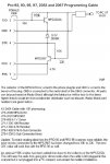
jack and expect both the TX and RX signals to appear at the tip. You cannot hook the TX and RX signals together at the tip without some controlling electronic circuit such as the one pictured above.Also scanners use TTL circuits that run at 5 volts or 3.3 volts and computer RS232 ports operate at 12 volt signal levels. So the extra elcectonics on the cable also have to change the voltage level presented to the scanner.
spokehedz
Member
The above circuit does use a RS232 com port and USB is not involved.
The Pro-97 era RS scanners have a TS (“mono”) jack and expect both the TX and RX signals to appear at the tip. You cannot hook the TX and RX signals together at the tip without some controlling electronic circuit such as the one pictured above.
Also scanners use TTL circuits that run at 5 volts or 3.3 volts and computer RS232 ports operate at 12 volt signal levels. So the extra elcectonics on the cable also have to change the voltage level presented to the scanner.
Well... Why not use a MAX232 to convert the signal levels?
Maxim QuickView - MAX220, MAX222, MAX223, MAX225, MAX230, MAX231, MAX232, MAX232A, MAX233, MAX233A, MAX234, MAX235, MAX236, MAX237, MAX238, MAX239, MAX240, MAX241, MAX242, MAX243, MAX244, MAX245, MAX246, MAX247, MAX248, MAX249 +5V-Powered, Multic
Seems that the only thing we have to figure out is the pinout of the 'stereo' cable.
Anybody? My radio is on order, coming in a few days.
Evert
Member
The pro-97 expects both the TX and RX signals at the tip of the plug, and the plug can be TS(mono) or TRS(stereo). That is what the cable above provides at the tip of its TS plug and the more modern RS 20-047 cable provides at the tip of its TRS plug when working in half duplex mode..
I think It is going to take a more complex circuit than just using a MAX232 chip. to interface between an RS232 port and the Pro-97. You can do a loop back test by tying the TX and RX on the Max232 togeather but I don't know if tying them togeather would work when the cable is connected between computer and scanner. I suppose if the supporting software could sort out what is loopback and what is being sent by the scanner, it might work.Maybe you can try it and let us know if it works.
But why start with an RS232 port? They are almost extinct. Why not get the RS 20-047 cable or the GRE equivalent?
Last edited:
spokehedz
Member
Mainly because they are expensive, and I thought it would be a simple issue of hacking a cable with the MAX232.But why start with an RS232 port? They are almost extinct. Why not get the RS 20-047 cable or the GRE equivalent?
Apparently, I was mistaken.
Programming cables
I am fairly certain you need an open collector type output to the radio. The existing cables work on quite a few different radios, some that are 5 volts and some that are 3.3 volts. I am not certain if any of the MAX232 ICs (there are a lot of them) provide an open collector output. Additionally there may be a polarity reversal of the signal that the traditional cable handles.
There are also ICs out there that handle the USB side of things too and give you "TTL level" serial signals. Why not use one of them and make it a USB cable instead of the RS-232 cable the MAX232 would be? Otherwise what are you going to do to get a COM port - use one of those cables you can buy for $5? It all depends on your motive.
I guess it depends on what your intentions are. Are you trying to save a couple of dollars or are you interested in doing this to show yourself that it can be done? By the time you buy components, build the cable and test it, you will have spent quite a bit of time on it. Certainly it can be done.Well... Why not use a MAX232 to convert the signal levels?
Seems that the only thing we have to figure out is the pinout of the 'stereo' cable.
I am fairly certain you need an open collector type output to the radio. The existing cables work on quite a few different radios, some that are 5 volts and some that are 3.3 volts. I am not certain if any of the MAX232 ICs (there are a lot of them) provide an open collector output. Additionally there may be a polarity reversal of the signal that the traditional cable handles.
There are also ICs out there that handle the USB side of things too and give you "TTL level" serial signals. Why not use one of them and make it a USB cable instead of the RS-232 cable the MAX232 would be? Otherwise what are you going to do to get a COM port - use one of those cables you can buy for $5? It all depends on your motive.
Evert
Member
My radio is on order, coming in a few days.
What model is your radio? I have been assuming it is a Pro-97. The story may be a little different if it is a newer model.
Evert
Member
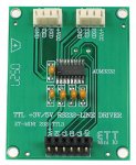
ETT RS232 to TTL-3V Converter Mini Board
I have been looking at the ETT RS232 to TTL-3V Converter Mini Board pictured below.
I think it might work for newer scanners such as the Pro-164 that operate using the tip of a TRS plug for TX and the ring for RX.
It may work for scanners such as the Pro-97 that use the tip for both TX and RX provided the programming software can deal with the echo of the data it sends out.
I saw one site that sells if for about $5.00
http://www.micropik.com/PDF/MINIRS2323v.pdf
Attachments
Last edited:
spokehedz
Member
I did not notice that this thread started out as a PRO-97 cable thread, but I have a PRO-163 arriving soon.
Basically, I know that the cable from RS is going to be very cost effective for most people who have many radios and who need to switch between them quickly for programming.
I also know that I have a big pile of IC's and connectors on my workbench, and if it is just serial data then there should be no reason why I cannot take a RS232 cable and wire up a 3.5mm jack for some quick programming rather than spending the cash on it now.
I realize that not everybody has a junk pile/workbench but for those that do... it would be nice to know what the pinout/schematic would be to make one.
Evert
Member
I have a PRO-163 arriving soon.
..........
I realize that not everybody has a junk pile/workbench but for those that do... it would be nice to know what the pinout/schematic would be to make one.
Having a Pro-163 may simplify things a bit. It uses a TRS(stereo) jack at i's PC/IF port and so you would use a TRS plug on your cable. Since it and the Pro-164 will work only with a TRS plug, I think it is fairly certain that the TS and RS signals are individually sent to the Tip and Ring sections, unlike both being sent to the Tip as with the Pro-97.
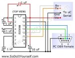
If one of your MAX chips has 3volt TTL ability a circuit similar to the one below may work.
I am not sure if the TX and RX shown are from the viewpoint of the computer or from the other device.
I would try first connecting TX to the Tip and RX to the Ring section of your cable’s TRS plug. Connect the sleeve section to the ground (Gnd) in the circuit below.
You will need a 5volt source for VCC – one way is to bring out a wire from a spare power connector inside your computer.
Ignore the “To uC Serial” wording.
Attachments
Last edited:
Evert
Member
After studying some MAX data sheets I see that the TX and RX in the above schematic is referenced from the scanner side. So pin 12 of the MAX should be connected to the Tip of the TRS plug and pin 11 should be connected to the Ring section. (Opposite of what I said before.)
PRO-97 cable vs PRO-164 cable
The cable for which I posted the schematic above just uses a couple of transistors to change the voltage levels. It should be noted that RS-232 is a +/- 12 volt signal (24 volt change). The PRO-92 (which the above cable works with as well) uses 5 volt technology and the later scanners use 3.3 volt technology.
One could just take the above cable and separate TX from RX for a lot less $$$ than using a MAX232 IC. Plus you will have the additional problem of where to get power for the MAX232.
Looking at your MAX232 design; pins 11 & 12 are 5 volt TTL level signals. The scanners (newer than the PRO-92) are 3.3 volt!!!! Also I wonder where you expect to get 5 volts to power the MAX232. Certainly you could steal it from a USB port, but now you need 2 cables to the PC.
Suggestions: don't be so fixated on using a MAX232. You will find it cheaper to use the original schematic, separate TX & RX, and use the correct plug. If you do decide to use a device like the MAX232, make a better selection (the board posted by Evert looks like is could be a 3.3v device). There are newer similar devices which do not require as many external capacitors. I'd be surprised if there is not a 3.3 volt version. Ideally you want open collector outputs anyway.
Last edited:
Evert
Member
gmclam, I have been looking for circuits using a MAX RS232 type chip because spokehedz said “why not use one” and mentioned wanting to use some of the “many ICs” he has in his junk box. I assumed that some of them are MAX ICs.
“The scanners (newer than the PRO-92) are 3.3 volt!!!! "
That is why I told spokehedz “If one of your MAX chips has 3volt TTL ability ….” .
There are definitely MAX RS232 chip versions that have 3.5 volt level on the TTL side. We need to know exactly what versions he has in his junk box.
As to adapting the original circuit you posted by separating the TX and RX, dosen't it have a 5 volt signal level on the scanner side? I would think it would not be useable for his Pro-163 either.
I have seen some circuits that provide 3.5 level signals by using two transistors plus a logic IC but was waiting to see what spokehedz has to say about his MAX chips before going to that.
“Also I wonder where you expect to get 5 volts to power the MAX232. Certainly you could steal it from a USB port, but now you need 2 cables to the PC".
I mentioned that one way is to bring out a separate wire from an unused power connector. I think that would be better than tapping a USB port for power. Yes an extra wire to connect is a bit awkward but would work ok for a situation where a programming cable is attached to one computer and left there. It has the advantage of not needing any other electronic components.
If he has the right components (he seems adamant about using only stuff from his junk box) there is a circuit that taps the RTS and DTR signals on the DB9 and uses a couple of capacitors and a TTL logic chip to provide 5 volt power to the MAX chip. I will post that if he is interested in doing it that way.
However, some folks advise against tapping the RS232 port for power and prefer to add an external power source. To do that you can use a junk box power cube and put a 5 volt voltage regulator on the circuit board of your programming cable.
"the board posted by Evert looks like is could be a 3.3v device"
It is definitely “Suitable for standard TTL 3V”.
It only costs $4.90 at http://www.futurlec.com/Mini_RS232_TTL_3V.shtml and I think that is a good way to go. I am thinking about ordering a couple to tinker with even though my entire basement is a huge junk box.
Looks like you can get the chip and circut board for less that just a chip would cost separately.
It needs VCC to be supplied but I am ok with that.
The description talks about a MAX232 chip but the picture shows an ADM3232 - I am not sure what is up with that and plan to email them to see what I actually would get.
Last edited:
- Status
- Not open for further replies.
Similar threads
- Replies
- 5
- Views
- 474