Red-dog,
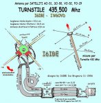
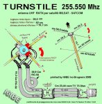
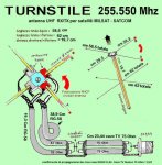
What is unclear about the balance? The MT article mentions dipole elements A and B get the long coax using connector E and dipole elements C and D get the short coax using connector F. The coax center goes to dipole elements B and D if assembled correctly.
The X-wing RG-6 coax is providing a 90 degree phase shift between dipole pairs and also helping to match them to a single 50 ohm feedline. The method used in the MT article is much easier to build and will accomplish the same as the example you show.
Thanks to Ozi for pointing out the matching in the example is probably a calculated starting point and the dimensions could be off by more than enough to degrade matching and circular polarity due to differences in coax velocity factor.
At the 260MHz frequencies we're dealing with, exposed center conductors and cable lengths become critical and its much easier and more accurate to (precisely) measure RG-6 from the article dimensions, install F connectors and your done. Cutting and splicing coax and especially foam filled RG-6 with foil shield and hardly any braid to solder is not recommended at these frequencies.
The MT X-wing when built with the recommended parts should be very repeatable, several prototypes were made for the article and all work very well.
prcguy
I'm building the x-wing but the original plan is unclear about the balance of the coaxial line on the dipoles, the net I found this another example, what do you think of this solution, someone can be more clearly explained if there is a difference between the two solutions?

")