How to ground under these circumstances

Status
Not open for further replies.

stealth71

Member
Joined
Oct 11, 2008
Messages
26
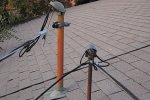
I'm going to be mounting a 10 foot mast on the roof of the house. I have read about all I can read about grounding in a 24 hour period. I understand how to ground the mast, lightning arrestors, cable size, etc.

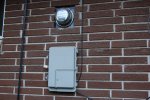
However it is my understanding that I also need to bond the antenna system to the house power grounding system. There is no way for me to do that outdoors as far as I can tell. My power comes from overhead wires to a service entrance on the roof, then into the house. The only thing visible on the outside is the meter, and even there all I can see is the glass cover. In other words, there is no metal to connect any ground cable to on the outside of the home.

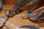
On the inside however, the main electrical ground is a heavy gauge copper wire that runs from the panel upstairs to the main cold water pipe in the basement. So, is that where I should connect the antenna system to the house power grounding system using some 6 AWG or larger, or am I not getting this right? Any help is appreciated.
 

Sinister

Member
Premium Subscriber
Joined
Sep 5, 2008
Messages
350
Location
New Hampshire
There are a couple of people here who will better answer your question, but how old is the house you are living in?
Most grounding for the electrical service is done usually by driving an 8ft copper rod in the ground below where the meter is located outside.
If you search this forum you will find alot of info on grounding ie..http://www.radioreference.com/forums/showthread.php?p=407543#post407543
 
Last edited:

stealth71

Member
Joined
Oct 11, 2008
Messages
26
Thanks for replying, Sinister. The house was built in 1968. I agree about the meter. The house is all brick, so all that is visible of the house's electrical system is the meter itself. Everything else is behind the brick, so I'm a little unsure how to bond the antenna system to the power system aside from running a cable to the cold water pipe, which is where the electrical panel appears to be grounded to. It may be a little hard to understand, so I attached a photo of where my electrical meter is located outside. The box below that is just a cable TV enclosure.
 

Attachments

  • DSC_1574.JPG
    DSC_1574.JPG
    94.8 KB · Views: 1,036

stealth71

Member
Joined
Oct 11, 2008
Messages
26
If I'm reading this attached diagram correctly, this is essentially what I have at my house as the electrical panel is bonded to the cold water pipe, and then there is a jumper from the antenna ground rod to the cold water pipe as well. Right now I don't have a ground rod, but from what I'm gathering here, this is essentially what I would need to do. Anyone have any opinions to offer? I know there is probably definitive information in the NEC code book, and I'm planning on getting a copy to review, but I just wanted to see what any of you think.
 

Attachments

  • DiagSafe.gif
    DiagSafe.gif
    34.4 KB · Views: 4,920
C

comsec1

Guest
cold water pipe

there should be a seperate 8' ground rod, the quality of the water pipe is not a good ground if there are any couplers or joints of any kind. there probably is at least 1 shut off.
 

stealth71

Member
Joined
Oct 11, 2008
Messages
26
there should be a seperate 8' ground rod, the quality of the water pipe is not a good ground if there are any couplers or joints of any kind. there probably is at least 1 shut off.

That's true, however from what I understand, it's OK to use the cold water pipe so long as the ground cable is attached within 5 feet of the pipe entering the house. The existing power ground is attached about 6 inches from the concrete floor and before any valves.
 

delta_p

Member
Joined
Dec 24, 2007
Messages
135
Thanks for replying, Sinister. The house was built in 1968. I agree about the meter. The house is all brick, so all that is visible of the house's electrical system is the meter itself. Everything else is behind the brick, so I'm a little unsure how to bond the antenna system to the power system aside from running a cable to the cold water pipe, which is where the electrical panel appears to be grounded to. It may be a little hard to understand, so I attached a photo of where my electrical meter is located outside. The box below that is just a cable TV enclosure.

My house, built in 1992 and all brick, is similar in that the house ground was not at the meter/box. My meter/box is in one section of a flowerbed which is enclosed by a sidewalk and one side of my garage. The switch panel in my house is located inside on the back wall of the garage on the same side of the house as the meter/box. Based on this I hunted the ground rod down in that flower bed. It should be near the meter/box regardless. I got a small shovel and probed, prodded, and dug around along the garage side of the flowerbed down at the foundation level until I found copper line going into the foundation. At the other end of that was the rod which ended up about 15feet from the meter/box at the other end of the flower bed. Turns out this was only about 4 ft from where I dropped my equipment ground rod coming out of my radio room so I tied the two together. I verified this was in fact the house ground (plus I found the phone ground clamped to the copper line) with using a meter.

PP
 

Sinister

Member
Premium Subscriber
Joined
Sep 5, 2008
Messages
350
Location
New Hampshire
Just curious, I notice in the picture a cable box below the meter. Is there a grounding block for the cable before running into the cable box if so there is usually a grounding wire running from the block to the copper rod.
 

jim202

Member
Joined
Mar 7, 2002
Messages
2,735
Location
New Orleans region
The NEC (National Electrical Code) stipulates that there be a ground at the meter. I would
be willing to bet a good sum of money that if you took a shovel and dug around in the ground
under the meter, that you would find the copper wire and follow it to the ground rod.

No electrical inspector will let the meter ground slip past him on a new install.

Jim


There are a couple of people here who will better answer your question, but how old is the house you are living in?
Most grounding for the electrical service is done usually by driving an 8ft copper rod in the ground below where the meter is located outside.
If you search this forum you will find alot of info on grounding ie..http://www.radioreference.com/forums/showthread.php?p=407543#post407543
 

stealth71

Member
Joined
Oct 11, 2008
Messages
26
Just curious, I notice in the picture a cable box below the meter. Is there a grounding block for the cable before running into the cable box if so there is usually a grounding wire running from the block to the copper rod.

I was trying to remember that as well. Another photo might help. For the cable TV, the cable comes from the pole to the eve of the house, then down the brick wall in to that gray box, then back up the wall and into the service entrance up on the roof. In the attached image, there is the electrical service up top. Both the CATV and phone enter through the smaller service entrance, with CATV wire on the left, phone on the right. The other cable laying there on the roof is the old satellite cable no longer in use. After the CATV wiring enters the service entrance on the roof, it just comes straight downstairs to the splitters. Should I perhaps inquire about this to the cable company?

So I don't see any ground outside for anything. I know there is not one anywhere around that gray box because I remember when they installed it. They just screwed it to the wall. There is something inside of it, but its all locked up, so I don't know what it is, but I do know nothing exits the box other than the CATV cables.

Getting a little off topic though. Still trying to determine how to bond the antenna system to the power ground.
 

Attachments

  • DSC_1576.JPG
    DSC_1576.JPG
    157.8 KB · Views: 1,089

stealth71

Member
Joined
Oct 11, 2008
Messages
26
The NEC (National Electrical Code) stipulates that there be a ground at the meter. I would
be willing to bet a good sum of money that if you took a shovel and dug around in the ground
under the meter, that you would find the copper wire and follow it to the ground rod.

No electrical inspector will let the meter ground slip past him on a new install.

Jim

Thanks Jim, I'll certainly look. This is all I can find so far. Hope you all don't mind all the photos, but I'm just trying to make sense of all of this, so I figure some photos will help. First photo shows a bare copper ground wire coming from the electrical panel upstairs to the basement. The other photo shows the other end of that wire attached to where the cold water main enters the house through the basement cement floor. Total distance run is about 35 feet or so. Its hard to see, but the wire wraps around the water pipe and then is secured with a clamp on the back side. Sorry for the crappy lighting as I was holding a flashlight while trying to take a photo.

So is it possible this is the only ground, or is it normal procedure to have a ground from the breaker panel to a water pipe, AND an additional ground to a ground rod outside. If that's the case, I guess I should start digging or something to see if I can find it.
 

Attachments

  • DSC_1580.JPG
    DSC_1580.JPG
    94.4 KB · Views: 931
  • DSC_1586.JPG
    DSC_1586.JPG
    82.2 KB · Views: 1,036

04Z1V6

Member
Joined
May 3, 2008
Messages
778
Location
Castle Rock, Co.
No part of the NEC says this. The NEC does say that your system must be Grounded and bonded at the first disconnecting means , this is why you see the cold water, building steel, ufer, and ground rod all brought to your main panel or disconnect. If you are not having an inspection a cold water ground on any part of a copper house pipe system would be fine you are not carrying any large amperage load to the grounding electrode you are just trying to equalize the potential at all grounded points. If anyone thinks you can control how lighting will travel they are mistaken. Lighting protection systems are not governed by the NEC because UL can not list a system that is proven to work, they are only working therry.
 

Sinister

Member
Premium Subscriber
Joined
Sep 5, 2008
Messages
350
Location
New Hampshire
Im not an electrical expert to tell you if thats your ground. But I will say that my house which was built in 1963 also has a copper wire but much larger than the one you have pictured I would guess probably 4 guage attached to the pipe for the water meter which goes under ground.
As of about 5 years ago, I had my electrical service panel upgraded to 200 amp and in doing so probably required the copper ground to be installed near the meter. So it may be possible that older houses had the ground installed to plumbing. So I will have to defer to the electrical experts on that one.
 

stealth71

Member
Joined
Oct 11, 2008
Messages
26
No part of the NEC says this. The NEC does say that your system must be Grounded and bonded at the first disconnecting means , this is why you see the cold water, building steel, ufer, and ground rod all brought to your main panel or disconnect. If you are not having an inspection a cold water ground on any part of a copper house pipe system would be fine you are not carrying any large amperage load to the grounding electrode you are just trying to equalize the potential at all grounded points. If anyone thinks you can control how lighting will travel they are mistaken. Lighting protection systems are not governed by the NEC because UL can not list a system that is proven to work, they are only working therry.

Yeah I don't want to be over-analyzing this too much. I want it to be safe and done correctly, but I guess it goes back to the original question, which is how to attach a ground jumper from my new grounding rod the the house power ground. Given the information provided, would I just run the wire from the rod to the cold water pipe shown in the photo above? If so, any suggestions on the size of the cable? I know I've read 6AWG. Can it be either solid or stranded? Stranded would make things a little easier.
 

stealth71

Member
Joined
Oct 11, 2008
Messages
26
Im not an electrical expert to tell you if thats your ground. But I will say that my house which was built in 1963 also has a copper wire but much larger than the one you have pictured I would guess probably 4 guage attached to the pipe for the water meter which goes under ground.
As of about 5 years ago, I had my electrical service panel upgraded to 200 amp and in doing so probably required the copper ground to be installed near the meter. So it may be possible that older houses had the ground installed to plumbing. So I will have to defer to the electrical experts on that one.

You could be right, Sinister. I've lived in this house since 1985, and I have never seen a ground rod or anything like it near where the meter is. But then again, I've never really gone looking for it. Maybe when the crappy weather clears up I will.
 

Sinister

Member
Premium Subscriber
Joined
Sep 5, 2008
Messages
350
Location
New Hampshire
Good luck and happy hunting.
Another option is to call in some one who installs antennas to inspect it or just have them give you a quote on doing the install. Just search your area for antenna installers.
 

04Z1V6

Member
Joined
May 3, 2008
Messages
778
Location
Castle Rock, Co.
If you use the optional 8' ground rod you must bound from the panel ground to the rod, one way to do this would be to set a separate ground clamp on you cold water pipe or split bolt to the #6 bare wire in the pic. Just a side note the clamp although acceptable at the the time your house was built should be replaced, get a good UL LISTED pipe clamp remove all paint with a wire brush and attach the ground wire from your panel to a new ground clamp also. SHUT OFF ALL POWER BEFORE YOU REPLACE the old clamp.
 

stealth71

Member
Joined
Oct 11, 2008
Messages
26
If you use the optional 8' ground rod you must bound from the panel ground to the rod, one way to do this would be to set a separate ground clamp on you cold water pipe or split bolt to the #6 bare wire in the pic. Just a side note the clamp although acceptable at the the time your house was built should be replaced, get a good UL LISTED pipe clamp remove all paint with a wire brush and attach the ground wire from your panel to a new ground clamp also. SHUT OFF ALL POWER BEFORE YOU REPLACE the old clamp.

So you're saying the existing panel ground is fine where it is on that pipe, however the clamp itself ought to be swapped out?
 

04Z1V6

Member
Joined
May 3, 2008
Messages
778
Location
Castle Rock, Co.
I am saying that we would not be able to use this type of clamp today they are not real good and it wouldn't hurt (for a small amount of money) to upgrade it and clean the connection point up. Article 250-66 of the NEC goes a little like this if your service entrance conductors are Copper #2or smaller = #8, #1 to 1/0 #6, and 2/0 to 3/0 #4 grounding electrode conductor. The NEC allows for a #10 conductor but not smaller then the lead-in conductor if for a transmitting station the conductor shall be not less then #14. This being said I would use a conductor that matches the size of the largest grounding electrode conductor to get less resistance to ground.
 

stealth71

Member
Joined
Oct 11, 2008
Messages
26
I am saying that we would not be able to use this type of clamp today they are not real good and it wouldn't hurt (for a small amount of money) to upgrade it and clean the connection point up. Article 250-66 of the NEC goes a little like this if your service entrance conductors are Copper #2or smaller = #8, #1 to 1/0 #6, and 2/0 to 3/0 #4 grounding electrode conductor. The NEC allows for a #10 conductor but not smaller then the lead-in conductor if for a transmitting station the conductor shall be not less then #14. This being said I would use a conductor that matches the size of the largest grounding electrode conductor to get less resistance to ground.

Is there any particular type of clamp that I should look for? Something I can just buy at Home Depot? I'm sure I can easily swap it out, looks pretty easy to do?
 
Status
Not open for further replies.
Top