Not content to leave well enough alone and with some time on my hands, I basically bent the full-wave dipole into something different:
http://www.radioreference.com/forum...l-wave-vhf-vertical-dipole-working-great.html
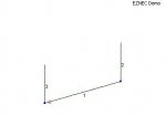
I created a vertical half-square by bending this antenna horizontally with the 1/4 wave ends hanging down. The feedline is now at the top corner, the 1/4 wave element from the braid hangs straight down. The long wire connected to the center conductor runs horizontally for a 1/2 wavelength, and the last 1/4 wave section hangs down again. Kind of looks like a 2-element beam.
(Pictures don't do this justice as it is currently made out of white zip-cord hung in front of white walls, with temporary hookups.")
I haven't modeled this or analyzed it any further, so if someone wants to run with it - great!
The thing I didn't notice until I hung it up is that I can utilize the common-mode braid current as a third element! Two-antennas-in-one depending on where you choke the feedline!
As it stands now, the feedline is choked at the corner feedpoint. BUT, if I remove the choke, and run the feedline away from the corner for a half-wavelength, and let the rest of the feedline hang down vertically, I now have what looks like a 3-element beam.
I'm now playing with putting the choke 3/4 wave away from the feedpoint down on the vertical section of the feedline to emulate a 3rd wire.
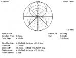
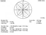
Well, this seems to be a bit esoteric, especially with what looks like three 1/4 waves inline with each other - expect a somewhat high look with gain - where - I don't know yet.
At least it is easy to build and tear down so there's no evidence.
Update: oops - it might be better to have the horizontal section become the bottom of the elevated half square rather than being at the top -- more testing....
http://www.radioreference.com/forum...l-wave-vhf-vertical-dipole-working-great.html
I created a vertical half-square by bending this antenna horizontally with the 1/4 wave ends hanging down. The feedline is now at the top corner, the 1/4 wave element from the braid hangs straight down. The long wire connected to the center conductor runs horizontally for a 1/2 wavelength, and the last 1/4 wave section hangs down again. Kind of looks like a 2-element beam.
(Pictures don't do this justice as it is currently made out of white zip-cord hung in front of white walls, with temporary hookups.
I haven't modeled this or analyzed it any further, so if someone wants to run with it - great!
The thing I didn't notice until I hung it up is that I can utilize the common-mode braid current as a third element! Two-antennas-in-one depending on where you choke the feedline!
As it stands now, the feedline is choked at the corner feedpoint. BUT, if I remove the choke, and run the feedline away from the corner for a half-wavelength, and let the rest of the feedline hang down vertically, I now have what looks like a 3-element beam.
I'm now playing with putting the choke 3/4 wave away from the feedpoint down on the vertical section of the feedline to emulate a 3rd wire.
Well, this seems to be a bit esoteric, especially with what looks like three 1/4 waves inline with each other - expect a somewhat high look with gain - where - I don't know yet.
At least it is easy to build and tear down so there's no evidence.
Update: oops - it might be better to have the horizontal section become the bottom of the elevated half square rather than being at the top -- more testing....
Last edited by a moderator: