Hme brewed 4-bay UHF dipole array

Status
Not open for further replies.

Skypilot007

Member
Premium Subscriber
Joined
Dec 26, 2005
Messages
2,541
Location
Medford, NJ
Big thanks first to prcguy for posting up the project that he designed a while back. See the thread below for all the details of construction.

http://forums.radioreference.com/antennas-coax-forum/109144-4-bay-vhf-dipole-array-project.html

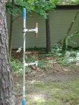
I just changed the demensions for UHF with a little exception and the rest is basically the same. I built it for a center frequency of 467.000MHz. I ended up having to cut the elements a bit shorter than what I calculated for the given frequency, perhaps I was off a bit on the phasing harness. I didn't alter those except they were cut per the design for 467MHz. I basically tuned each dipole individually the best I could with a radio, swr meter and a couple 8ft lenths of RG8X 50ohm cable connecting the two. Each dipole showed the same charastics, it wanted to be shorter than the calculated lenth. Perhaps it wanted to be a bit longer, I don't know and I didn't have any more copper pipe around so I started trimming with good results on the swr meter. I tuned the other three dipoles the same way. I then tested two of the dipoles connedted to a aluminum extendo painting roller out in the yard and that went well. Then I tested all 4 mounted and spaced correctly on a 10ft piece of 1" steel conduit and it tuned right up.

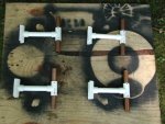
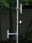
I also used 50 ohm RG8X for the phasing harness with F connectors and common cable TV spliters. I need to get a couple more smaller spliters to clean it up a bit. I painted it grey primer and put some caps on the elements with weep holes in the bottom caps. Hot glued the lug connections were the coax from the phase cable attaches to the elements. I had the antenna jammed into the ground surrounded by trees and it was receiving nearly as well as the tram antenna up on the roof.

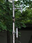
I did 3 swr tests with the antenna to verify the swr results I was getting and the general performance. I tested the antenna from 440-480MHz outside in the yard feed with short runs of RG8X, then as a two-pole array in the attic for a few weeks feed with 12ft of beldon 9913, and finally on my roof feed with about 40ft of LMR400. All the swr results were nearly the same. Between 440-480 the highest swr was 1.8:1 which was at 440MHz. It has nearly a flat swr from 444-449 the varies a bit thru 455 then is nearly flat again thru 480. I can't explain it but I'm not complaining. It receives better than the tram did mounted in the same location about 10ft lower. I'm pretty happy with it so far. Some pics below.
 

Attachments

  • P7052525.JPG
    P7052525.JPG
    171.2 KB · Views: 8,793
  • P7052527.JPG
    P7052527.JPG
    182.7 KB · Views: 8,023
  • P7062551.JPG
    P7062551.JPG
    168.5 KB · Views: 7,244
  • P7062544.JPG
    P7062544.JPG
    152.6 KB · Views: 7,355
  • P7062545.JPG
    P7062545.JPG
    156.1 KB · Views: 8,006

prcguy

Member
Joined
Jun 30, 2006
Messages
15,339
Location
So Cal - Richardson, TX - Tewksbury, MA
A couple of comments.

The elements will come out a bit shorter than calculated especially at UHF because of the large diameter pipe and the element actually starts where the coax splits.

You must use 75ohm coax for the phasing harness.

The dipoles look a bit far out from the mast, for UHF they would about 6" out from the mast to the center of the dipole worst case and usually mfrs place them much closer. Whatever the spacing was in the VHF version divide that by 3 for UHF and it will be close enough.

You must use 75ohm coax for the phasing harness.

You cannot use TV splitters, you must use a T connector or even solder three junctions of coax together. Each TV splitter has more than 3dB loss so two sets of them eat up all the gain of the antenna and then some. You can use SO-239 style T adapter and PL-259 connectors on RG-59 coax or L-Comm has nice F type T adapters for around $3 each.

Did I mention you MUST use 75 ohm coax for the phasing harness?

Otherwise its a really nice job.
prcguy
 
Last edited:

phatboy48

Member
Joined
Feb 6, 2009
Messages
40
Great job, nice looking antenna! Here's something to consider, it would be very easy to make this antenna into a dual-band system by cutting the dipole elements for VHF and using 75 ohm phasing harness cables cut to 1/4 wavelength at VHF. The VHF dipoles will also function well as 3/4 wavelength elements at UHF and the 1/4 wavelength sections of phasing harness also function well as 3/4 wavelength sections at UHF.

By using 75 ohm phasing lines, you also can directly splice them together without adding the insertion loss of the splitters. The cables act as linear impedance transformers and change the 50 ohm Z of each dipole into 100 Ohms at the open end. When you splice the two harness cables together, you are putting the two 100 Ohm points in parallel and are back to 50 Ohms again.

We used this trick on our UHF ham repeater for the receive sites. We would use the existing VHF 4-bay antennas at the sites for receive duty on the UHF system and they worked as well as UHF receive antennas.

W8JNC
 

Skypilot007

Member
Premium Subscriber
Joined
Dec 26, 2005
Messages
2,541
Location
Medford, NJ
I kinda knew the cable spliters were a bad idea but it was all I had lying around. I didn't realize they had that much loss each! Somehow someway this antenna performs very well. It has good ears and I can hit repeaters nearly 35-40 miles away so far. I'm gona redo the phasing harnesses with 75ohm cable and test with a 2-pole setup with the extra parts I have and see how that goes. I'll post that up when I get to it. Thanks again for the suggestions.
 

IdaScan

Member
Premium Subscriber
Joined
Nov 24, 2005
Messages
10
Location
Middleton, Idaho
Looks great! Just a heads up, I prefer a longer "Tee" than the typical stubby ones found on eBay. The ones sold through L-Com are great as they allow for a rubber weather bushing to fit on without major trouble trying to thread on the male F connector.

As always, make sure all of your F connectors are wrench tight on fitting to fitting; only connection typically that will be finger tight is at the back of the radio itself. If in doubt, 7/16" torque wrenches can easily be sourced from online vendors like Tech Tool Supply.

Do you have the exact dimensions you ended up using for the dipole elements and phasing harness?
 

Skypilot007

Member
Premium Subscriber
Joined
Dec 26, 2005
Messages
2,541
Location
Medford, NJ
I have a feeling that when I correct my antenna the SWR readings I was getting are going to change. When I install the L-com F type T connectors and redo the phasing harness with 75 ohm cable I'll post up my final dimensions. The way it is now the dipole elements are only 3 inches each which had me thinking that I cut it down to 1/4 wave antenna. The phasers are cut to lenth per pcrguys design except they are 50ohm RG8X.

Last night I was getting into a 440 repeater over 40 miles away with 25 watts with excellent reports. I'm almost affraid to touch it to fix it! Its working very well but I will attempt to fix it right and post results. If it goes bad I'll put it back how it is now regardless if its correct or not, it working for me.
 

prcguy

Member
Joined
Jun 30, 2006
Messages
15,339
Location
So Cal - Richardson, TX - Tewksbury, MA
I'm surprised the TV splitters haven't popped yet with that much power. Most are made like a transformer with a tiny ferrite bead as the core.
prcguy


I have a feeling that when I correct my antenna the SWR readings I was getting are going to change. When I install the L-com F type T connectors and redo the phasing harness with 75 ohm cable I'll post up my final dimensions. The way it is now the dipole elements are only 3 inches each which had me thinking that I cut it down to 1/4 wave antenna. The phasers are cut to lenth per pcrguys design except they are 50ohm RG8X.

Last night I was getting into a 440 repeater over 40 miles away with 25 watts with excellent reports. I'm almost affraid to touch it to fix it! Its working very well but I will attempt to fix it right and post results. If it goes bad I'll put it back how it is now regardless if its correct or not, it working for me.
 

IdaScan

Member
Premium Subscriber
Joined
Nov 24, 2005
Messages
10
Location
Middleton, Idaho
I'm surprised the TV splitters haven't popped yet with that much power. Most are made like a transformer with a tiny ferrite bead as the core.
prcguy

Exactly, I can't quite tell from the photo but they appear to be "gold plated" consumer grade splitters... Small ferite and a couple windings of 20 guage wire internally... What's even better is that they're actually backwards for reception - the return loss from the output leg to the input leg of a CATV splitter can be upwards of 20 dB (another reason not to hand out modems and splitters to customers at the front counter)... Ours are rated for the 3.5 dB loss per leg forward from 50 MHz - 1 GHz and 3.5 loss fon return from 4 to 45 MHz... They sweep to about 60 MHz before that 3.5 number goes through the roof...

What's even funner is "customer installed" directional couplers in backwards - signal on Tap leg, TV on input leg and modem on through leg.
 

IdaScan

Member
Premium Subscriber
Joined
Nov 24, 2005
Messages
10
Location
Middleton, Idaho
I have a feeling that when I correct my antenna the SWR readings I was getting are going to change. When I install the L-com F type T connectors and redo the phasing harness with 75 ohm cable I'll post up my final dimensions. The way it is now the dipole elements are only 3 inches each which had me thinking that I cut it down to 1/4 wave antenna. The phasers are cut to lenth per pcrguys design except they are 50ohm RG8X.

Last night I was getting into a 440 repeater over 40 miles away with 25 watts with excellent reports. I'm almost affraid to touch it to fix it! Its working very well but I will attempt to fix it right and post results. If it goes bad I'll put it back how it is now regardless if its correct or not, it working for me.

You used the design to calculate for UHF or used the same length as the VHF? Just wanting to make sure :)

That's awesome you're getting that far out - have you tried moving the dipoles in to the directional pattern for more gain?
 

Skypilot007

Member
Premium Subscriber
Joined
Dec 26, 2005
Messages
2,541
Location
Medford, NJ
I recalculated for UHF and cut everything for UHF but like I mentioned my elements are very short. By calculation they should be about 6" but mine are closer to 3". I have some more scaps of pipe my plumber friend left me so when I change the phasing harness and T's I can cut some new elements if needed.

I have left it configured as omni directional and will probably stay that way.
 

IdaScan

Member
Premium Subscriber
Joined
Nov 24, 2005
Messages
10
Location
Middleton, Idaho
Interesting, as I see it, each element of the copper pipe is roughly a quarter wave length long which comes out to about 6.25"... I'm curious if the coupling with your 50 ohm phasing harness and distance from the mast is causing the tuning to shift from half wave total length to quarter wave total length (tip to tip on each dipole).

Has anyone thrown this design in to EZNEC or any of the antenna modeling applications?
 

mcgiver

Member
Joined
Aug 20, 2009
Messages
8
Location
Italy
Hallo

One question: this UHF/VHF array have a eletric tilt? How many degree?
If not, is possible to make it?
 

prcguy

Member
Joined
Jun 30, 2006
Messages
15,339
Location
So Cal - Richardson, TX - Tewksbury, MA
Remember the elements start where the coax splits and that adds an inch or two to the element length. The individual elements are tuned using 50ohm coax and when the 75ohm harness is installed everything will fall into place. You should really use an antenna analyzer to tune the individual phasing harness sections if you use different coax than the original project or if you change the center frequency. I believe the VHF harness will work at exactly 3X the design freq so my 153MHz harness might tune around 459MHz. I have not proved this so someone should measure it with an analyzer.
prcguy

I recalculated for UHF and cut everything for UHF but like I mentioned my elements are very short. By calculation they should be about 6" but mine are closer to 3". I have some more scaps of pipe my plumber friend left me so when I change the phasing harness and T's I can cut some new elements if needed.

I have left it configured as omni directional and will probably stay that way.
 

Skypilot007

Member
Premium Subscriber
Joined
Dec 26, 2005
Messages
2,541
Location
Medford, NJ
Thanks for the addtional thoughts prcguy.

I haven't had any time to tinker with the antenna lately and its been raining alot. I tried to sneak up on the roof today between storms and sure enough another storm hits. I managed to get down and that was it.

I cracked open one of those cable tv splitters I used...scary! Live and learn.

I going to reconfigure with the 75ohm phasing sections and the L-comm T connectors. I'm going to cut it all for 450.000 MHz and hope it tunes up on 440 and gmrs. I was thinking when its constructed and tuned right it might exhibit the 20MHz or so band width instead of what I'm seeing now.
 

mcgiver

Member
Joined
Aug 20, 2009
Messages
8
Location
Italy
Hallo!
I'm going to make my first dipole for 431Mhz.
I use a 18mm copper pipe and each element is lenght 17,5 cm from coax splits; out from mast 5,4cm.
I have connected 1m rg58 for tuning single dipole with MFJ269 but SWR is >3!!!!

Please help me!!
 

IdaScan

Member
Premium Subscriber
Joined
Nov 24, 2005
Messages
10
Location
Middleton, Idaho
Hallo!
I'm going to make my first dipole for 431Mhz.
I use a 18mm copper pipe and each element is lenght 17,5 cm from coax splits; out from mast 5,4cm.
I have connected 1m rg58 for tuning single dipole with MFJ269 but SWR is >3!!!!

Please help me!!

At 431 MHz, your quarter wave elements are 16.5 cm long; this includes the small length of coax past where it's split. In reality, if you have 4 cm of coax split like the design, your dipole lengths will be closer to 14-15 cm long. Try trimming back your dipole elements 5 mm at a time until you have it dialed in - at UHF the diameter of the pipe will also affect overall length, resulting in a slightly shorter than calculated dipole.

Let us know what you come up with :)

Working off of the quarter wave calculator, prcguy's VHF dipole elements were 88.5% of the length of a full quarter wave at 153 MHz... i.e. 16 1/4" cut length is 88.5% of the 18.35" quarter wave length calculation.

Amateur Quarter Wave Ground Plane Antenna Calculator

Based on that, even though you'll be likely slightly shorter at UHF, 431 MHz is 16.5 cm x .885 = 14.6 cm copper pipe length (factors in the length of stripped back coax assuming you're starting with 1.5" or 3.8 cm from jacket to screw)
 

mcgiver

Member
Joined
Aug 20, 2009
Messages
8
Location
Italy
Thanks for your reply!!
This afternoon I try.

Two questions:
-distance from two copper pipe inside T is critical (now is 1 cm)?
-I check SWR from 420 to 460 Mhz with MFJ269 but is alwais >3 ... is normal?
-I solder coax split outside T (nearest) directly over copper pipe, is bad?
 
Status
Not open for further replies.
Top