Centerfire VHF/UHF Multi Band Base Antenna (Review)

Status
Not open for further replies.

joeuser

The Wretched
Joined
Feb 9, 2014
Messages
1,613
Location
North Central Kansas
This is my attempt to review this antenna from the Centerfire business. They appear to make not only scanner antennas but also HAM antennas. This will cover one specific model that I purchased a few days ago from the center fire antennas.com website found at this URL: VHF/UHF Multi Band | Centerfire Antenna My sole motive here is to review this & share it with readers @ RR. I am not being compensated in any way, I have no interests with this business. I am just a customer.

The base cost is 39.95 USD, however there is another option explored more below. Shipping is 5.75 to anywhere in the USA. I was checked out by way of PayPal.

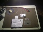
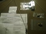
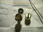
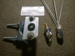
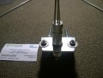
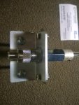
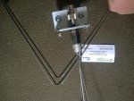
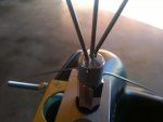
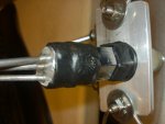
My order arrived quickly, by way of USPS priority mail, in one of those triangular boxes that the USPS will provide to shippers for free. It was rather beat up but it didn't seem to have any adverse effect on the unit. In a little box I found the SO-239 stud, a nylon ring, an UHF male to F type female adapter*, the pole mounting apparatus, instructions, a business card, & another business card with helpful but basic emergency preparedness information.

*The adapter is optional & the price with the adapter is 44.90 USD.
 

Attachments

  • WP_20150126_002.jpg
    WP_20150126_002.jpg
    54 KB · Views: 1,632

joeuser

The Wretched
Joined
Feb 9, 2014
Messages
1,613
Location
North Central Kansas
This is a close up of the antenna. Whips are made of a springy steel. Seemed to be solid & well constructed to me. I think I will drip a bit of Super Glue where the whips seat, just to seal them. The SO-239 stud is heavy. The mounting unit seems well built & of high quality. The instructions are easy to read & follow, although I didn't follow them.
 

Attachments

  • WP_20150126_003.jpg
    WP_20150126_003.jpg
    77.3 KB · Views: 1,483
Last edited:

joeuser

The Wretched
Joined
Feb 9, 2014
Messages
1,613
Location
North Central Kansas
This is the SO-239 stud. I had issues getting the UHF male adapter to seat in it, I tried another adapter from Radio Shack & had issues as well. At this time I had the chance to call for support. My call was answered by a pleasant, calm, clear speaking & helpful fellow. He quickly determined that there was an issue & suggested I just use a punch or something similar to just spread it open a bit. I did & once again, I was back on track. That ding was my fault, the first punch I grabbed was flat not pointed. Easy fix though for my own goof. You can also see the nylon ring that seats on top of the mount. The stud is seated through it. On the right is the included (optional) UHF male to F type female adapter.
 

Attachments

  • WP_20150126_004.jpg
    WP_20150126_004.jpg
    45.3 KB · Views: 1,479
Last edited:

joeuser

The Wretched
Joined
Feb 9, 2014
Messages
1,613
Location
North Central Kansas
Seen here is the antenna mount, the SO-239 stud, & the main vertical whip assembly. The nylon ring is now seated on the mount. The nuts, washers, & bolts above & below the black ring hold the downward angled antenna plane.
 

Attachments

  • WP_20150126_005.jpg
    WP_20150126_005.jpg
    90.4 KB · Views: 1,684
Last edited:

joeuser

The Wretched
Joined
Feb 9, 2014
Messages
1,613
Location
North Central Kansas
This is the completed assembly of the parts above. I'm considering sealing the whips with Super Glue, only as a preventive measure. It may not be needed.
 

Attachments

  • WP_20150126_006.jpg
    WP_20150126_006.jpg
    75.1 KB · Views: 1,575
Last edited:

joeuser

The Wretched
Joined
Feb 9, 2014
Messages
1,613
Location
North Central Kansas
Another view here but it's a "gripe". It just doesn't seem proper to use bolt heads like these. I would have expected them to be flat & flush with the mount. However, I have very little knowledge of these things, it just seemed off to me...
 

Attachments

  • WP_20150126_007.jpg
    WP_20150126_007.jpg
    52.6 KB · Views: 1,426
Last edited:

joeuser

The Wretched
Joined
Feb 9, 2014
Messages
1,613
Location
North Central Kansas
I love the concept for the bottom plane whips. All one piece, should be very durable. They seat on the bolts, underneath the washers and on the mount itself. I may use some JB Weld or CoAx Seal on these to keep corrosion from compromising the integrity between the plane whips & the mount. Im not sure if this will be needed or not though.
 

Attachments

  • WP_20150126_008.jpg
    WP_20150126_008.jpg
    98.7 KB · Views: 1,692
  • WP_20150126_009.jpg
    WP_20150126_009.jpg
    75.8 KB · Views: 1,432
Last edited:

joeuser

The Wretched
Joined
Feb 9, 2014
Messages
1,613
Location
North Central Kansas
Here is the completed antenna, left to stand on its own. Its very light but seems very durable.
 

Attachments

  • WP_20150126_010.jpg
    WP_20150126_010.jpg
    100.5 KB · Views: 1,584
  • WP_20150126_011.jpg
    WP_20150126_011.jpg
    107.7 KB · Views: 1,567
Last edited:

joeuser

The Wretched
Joined
Feb 9, 2014
Messages
1,613
Location
North Central Kansas
Construction of the antenna only took about 15 minutes, if that. With the exception of the adapter not readily seating into the SO-239 plug, everything went very well. The glitch was handled quickly & professionally. Hate when you call for support & they want to disagree &/or argue about things. This should never happen & delightfully didn't when I called Centerfire.

The only thing, so far, that is detracting from the entire experience, is the fact that I was forced to use an adapter. I would have wished that this antenna could have been made with the F connection. However, I will seal it all up & see how it does.

One more thing, minor, but seems weird to me. The mounting plane, where the stud seats for the main antenna whips... The mount has been angled, tapered, if you will... Why? Makes no sense. I appreciate no sharp edges but when you are trying to get the downward whips that form the bottom plane evenly, it makes it hard to keep them in alignment with one another. I wound up setting them flush to the widest section (towards the bend into the vertical section where the assembly bolts to the mast) but then I saw how the other end doesn't have the metal underneath for support...

Again, these things are minor. I'm not an engineer, machinist, or anything like that. I'm sure they will have no impact on performance. Its my nature to be CDO (That's OCD but far more serious because I put the letters in alphabetical order!) & meticulous about some things. These things just make me wonder...

I plan to mount this tomorrow afternoon & will follow up with anything of note. Hope you found this enjoyable, informative, & useful. That's exactly how I think of this forum & the majority of the users I have interacted with. Thank you!
 
Last edited:

joeuser

The Wretched
Joined
Feb 9, 2014
Messages
1,613
Location
North Central Kansas
Placeholder for continued review... From the final touches & actual install. I'll cover my results of using this antenna after sufficient time to put it through its paces.
 
Last edited:

Voyager

Member
Joined
Nov 12, 2002
Messages
12,060
One reason against the F connector - it's a 75 ohm connector, and that is a 50 ohm antenna (one of the few designs that really is 50 ohms). I'm sure it can be used for transmitting in the ham bands, so you would not want a 75 ohm connector which would throw off the match.

That said, nice review!

One question: Is the longest element going straight up? It doesn't look like it is in Post #8, but I think it may be an optical illusion. I would definitely want it going straight with the two shorter elements angled.

BTW, if you want to get extremely technical, only the vertical element will be 50 ohms - the others will be ever so slightly off 50 ohms.
 

Voyager

Member
Joined
Nov 12, 2002
Messages
12,060
What is the Connector Impedance?

Explains it pretty well. It doesn't determine the impedance of the line - it is a point in the line that has 75 ohm impedance. It would be like connecting a short run on RG6 then connecting that to RG8X. By design, the F connector is a 75 ohm connector. BNCs are even more wild, as there are both 75 ohm and 50 ohm versions. For the most part, they are even interchangeable, so you have to be careful to use the correct ones for the application.
 

joeuser

The Wretched
Joined
Feb 9, 2014
Messages
1,613
Location
North Central Kansas
One reason against the F connector - it's a 75 ohm connector, and that is a 50 ohm antenna (one of the few designs that really is 50 ohms). I'm sure it can be used for transmitting in the ham bands, so you would not want a 75 ohm connector which would throw off the match.

That said, nice review!

One question: Is the longest element going straight up? It doesn't look like it is in Post #8, but I think it may be an optical illusion. I would definitely want it going straight with the two shorter elements angled.

BTW, if you want to get extremely technical, only the vertical element will be 50 ohms - the others will be ever so slightly off 50 ohms.

Yeah, the center element is completely vertical. The other two elements are slightly angled away from the middle & vertical element.
 

joeuser

The Wretched
Joined
Feb 9, 2014
Messages
1,613
Location
North Central Kansas
What is the Connector Impedance?

Explains it pretty well. It doesn't determine the impedance of the line - it is a point in the line that has 75 ohm impedance. It would be like connecting a short run on RG6 then connecting that to RG8X. By design, the F connector is a 75 ohm connector. BNCs are even more wild, as there are both 75 ohm and 50 ohm versions. For the most part, they are even interchangeable, so you have to be careful to use the correct ones for the application.

I have read that the difference between 50 & 75 ohm is very minor in actual use (not in connections, but in use).
 

Voyager

Member
Joined
Nov 12, 2002
Messages
12,060
I have read that the difference between 50 & 75 ohm is very minor in actual use (not in connections, but in use).

For receiving, I would generally agree, but it does make a difference. For transmitting, it makes a big difference.
 

joeuser

The Wretched
Joined
Feb 9, 2014
Messages
1,613
Location
North Central Kansas
This is part of my attempt to better weather proof the connections. I'm not done, just doing a few steps at a time & considering the best approach to the next...

First pic is Loctite GO2 glue to better weather proof the top whips into the stud.

Second pic is CoAx Seal to proof the top part of the stud itself.
 

Attachments

  • WP_20150127_001.jpg
    WP_20150127_001.jpg
    27.5 KB · Views: 1,442
  • WP_20150127_002.jpg
    WP_20150127_002.jpg
    38.6 KB · Views: 1,307
Status
Not open for further replies.
Top