• To anyone looking to acquire commercial radio programming software:

    Please do not make requests for copies of radio programming software which is sold (or was sold) by the manufacturer for any monetary value. All requests will be deleted and a forum infraction issued. Making a request such as this is attempting to engage in software piracy and this forum cannot be involved or associated with this activity. The same goes for any private transaction via Private Message. Even if you attempt to engage in this activity in PM's we will still enforce the forum rules. Your PM's are not private and the administration has the right to read them if there's a hint to criminal activity.

    If you are having trouble legally obtaining software please state so. We do not want any hurt feelings when your vague post is mistaken for a free request. It is YOUR responsibility to properly word your request.

    To obtain Motorola software see the Sticky in the Motorola forum.

    The various other vendors often permit their dealers to sell the software online (i.e., Kenwood). Please use Google or some other search engine to find a dealer that sells the software. Typically each series or individual radio requires its own software package. Often the Kenwood software is less than $100 so don't be a cheapskate; just purchase it.

    For M/A Com/Harris/GE, etc: there are two software packages that program all current and past radios. One package is for conventional programming and the other for trunked programming. The trunked package is in upwards of $2,500. The conventional package is more reasonable though is still several hundred dollars. The benefit is you do not need multiple versions for each radio (unlike Motorola).

    This is a large and very visible forum. We cannot jeopardize the ability to provide the RadioReference services by allowing this activity to occur. Please respect this.

WACOM WP-641 Inter-Cavity Cable Lengths

Status
Not open for further replies.

902

Member
Joined
Nov 7, 2003
Messages
2,625
Location
Downsouthsomewhere
Greetings all,

I was given a Wacom WP-641 4 can VHF duplexer, but the catch is that there were no cables with it. I made RG-214 jumpers for another project and used them, but I'm having difficulty getting the duplexer to work in the system without severe desense. I suspect two issues - first, a critical cable length between the transmitter and the cavity, and second, the lengths of cable between the UHF T connectors isn't quite right.

For the first issue, I'm going to have to go out and buy a Z matcher or dig out a circulator. But for the second, I need to make new cables. Except Wacom is no more.

Anyone got the formula for these? I'm trying to get into the lower range of the 2 meter ham band and somewhat above/below - but close to - the 2 meter range.

Thank you!
 

zz0468

QRT
Banned
Joined
Feb 6, 2007
Messages
6,034
I'd suggest you post your question to the Repeater Builder yahoo group. Someone there probably knows the cable lengths you need.

The transmitter and receiver to duplexer cables aren't going to be critical. The others will be.
 
Last edited:

AK9R

Lead Wiki Manager and almost an Awesome Moderator
Super Moderator
Joined
Jul 18, 2004
Messages
9,361
Location
Central Indiana
Scroll about half-way down this page for info on Wacom duplexers. Maybe there's something in those documents that will help.
 

902

Member
Joined
Nov 7, 2003
Messages
2,625
Location
Downsouthsomewhere
Thanks, guys.

I spent a while last night messing with this. I think the first order of business is going to be a Tessco order for an impedance matcher. I padded the transmitter input of the duplexer with a 6 dB Thruline attenuator bringing the impedance to 50 ohms, and the desense issue got considerably better. I probably have a different length of 1/4" FSJ in the garage that might do, too. Or maybe one of the MASTR-II PAs has a matcher attached to it. Time to do some fishing (I didn't want to call it dumpster diving).
 

BirkenVogt

Member
Joined
Dec 8, 2005
Messages
370
Location
BirkenVogt
The inter cavity cable length is typically as follows: multiples of 1/2 wave minus the effective wavelength of the coupling loop inside the can on each end. How long is that effective wavelength? It is variable depending on the degree of coupling (insertion loss setting). In other words no one knows for sure.

One time we called a well known high quality filter manufacturer and asked them how they do it and their answer was they have a rack full of different length cables on the wall and they try them until it works correctly. This can get expensive doing it yourself with N connectors several bucks a pop but if you are careful and try to get it close with the math calcs at first it might be practical especially if you can find other uses for the "wasted" jumpers. I have done it this way.

Suffice it to say that it is usually better in time and money to find a filter setup that is already close in frequency/configuration to what you are trying to do and just make minor tweaks then to build it from scratch or spare parts of others. But this may or may not be helpful to your own situation right now.
 

zz0468

QRT
Banned
Joined
Feb 6, 2007
Messages
6,034
The inter cavity cable length is typically as follows: multiples of 1/2 wave minus the effective wavelength of the coupling loop inside the can on each end. How long is that effective wavelength? It is variable depending on the degree of coupling (insertion loss setting). In other words no one knows for sure.

The guy with the vector network analyzer and a Smith Chart knows for sure.

The electrical length of the loops can be measured, as can the complex impedance. Add a constant impedance line stretcher (General Radio 874 series) and the job goes from black magic to an easy hour of play time.

To the OP... Someone has done exactly what you want. Ask on Repeater Builder and you'll probably get the cable lengths.
 

902

Member
Joined
Nov 7, 2003
Messages
2,625
Location
Downsouthsomewhere
The guy with the vector network analyzer and a Smith Chart knows for sure.

The electrical length of the loops can be measured, as can the complex impedance. Add a constant impedance line stretcher (General Radio 874 series) and the job goes from black magic to an easy hour of play time.

To the OP... Someone has done exactly what you want. Ask on Repeater Builder and you'll probably get the cable lengths.
I certainly wish I had a VNA, but if I did find one on the used market, it would end up like my TDR, squirreled away for a once-every-couple-of-year site adventure, and my IR bonder which my son uses now more than I do. My UHF repeaters have essentially been set-and-forget with occasional trips to vacuum the bugs and spider webs out of the cabinet. This is my first foray into VHF with equipment that I own, as opposed to employer or client's equipment.

Virtually all of the website (not individual post) documentation will go to graphic details on physical dimensions of everything and deliberately avoid cable lengths, however I appreciate BirkenVougt's breakdown. Yes, this is certainly calculable and would vary based on VF of the cable, as well.

I am on Repeater-Builder, but you probably wouldn't recognize me there, as I post with my ham call sign, not as "902" (I think... it's been a while and I'm here more often). We've got a great and helpful bunch here, too, so I wanted to toss it out here first.

Thank you!
 

WA0CBW

Member
Premium Subscriber
Joined
Dec 8, 2011
Messages
1,635
Location
Shawnee Kansas (Kansas City)
I would find someone with a spec/analyzer/return loss bridge and do it right. As was said the cable from the transmitter to the duplexer isn't usually critical. I have several in service with that duplexer and they are different random lengths. Assuming you have "tuned" it per the directions I suspect it is the cable between cavities that is the issue.
BB
 

902

Member
Joined
Nov 7, 2003
Messages
2,625
Location
Downsouthsomewhere
From a factory-made 2 meter duplexer...

Thanks to a social media friend, I have a definitive answer for factory cables for the ham 2 meter band.

They are 11-3/4" long from the tip of the PL259 connector to the tip of the PL259 connector. This is presuming RG214 cable, with a velocity factor of 0.66.

IF all things hold true (and I didn't screw up in the calculation), this would equate to the electrical length of 14.6" of 1/4" FSJ (Vf of 0.82) from tip to tip if one were inclined to use FSJ cable for inter-cavity jumpers and jumpers from the furthest can to the UHF T connector out to the antenna. The transmitter cable length is also critical. I'm running an EMR Z-match (which took a very long time on back-order) to match the impedance of the PA to the cable and duplexer rather than playing with cable lengths.

I haven't tried the shorter length yet. The cables I was using were 12.5 inches long and I couldn't notch out enough transmitter noise enough to eliminate desensing. The next step for me is to put in an order, then make up some cables. I'll try those. If they don't completely work, step 2 would be disassembling the cavities at the rivets and cleaning the finger stock on the plunger, then thinly coat the joints with Nye Rheolube 362 HT (if my small quantity order ever ships in...). And, if that doesn't work, new transmission line and antenna. At that point, I'd have serviced or changed out virtually everything except the repeater's transmitter, itself (which the manufacturer assures me "it's not the transmitter"). We'll see.

Thank you everyone!

(Hope this will solve a future problem for someone else searching around.)
 

jeatock

Member
Premium Subscriber
Joined
Jul 9, 2003
Messages
599
Location
090-45-50 W, 39-43-22 N
Same situation, sorta, on a set of filters gifted to my local ham club. Now I know why Wacom is a step-child. I did find the tuning instructions, but other technical documentation had evaporated. Reading somewhere that the factory trial-and-error'd different lengths until they found a set that worked was not encouraging.

The interconnect cables were water logged and the TX/RX 'T' broken (long story). TX loss was over 6db and RX was hopeless. Blew the cavities out with dry nitrogen over a weekend. I made new jumpers of the same length as the originals out of RG142. Good guess vs. technical expertise. Changed to N connectors on the T and outwards. RX was almost tolerable, but TX loss was still 3db. Tried different jumper lengths with no appreciable change, so I went back to the original lengths. TX input lead length was a pain as well, and I ended up with only a minor change.

So far, I was not impressed.

In service was lackluster. I read several places that 2.5~3db insertion loss was not unusual for this duplexer, so I let it be.

I had a midnight epiphany: this site already had a nice unfiltered multicoupled RX antenna at 100' (the 2-meter antenna was at 40'). I went back in and disconnected the duplexer, re-configuring it as a receive notch filter through the 100' antenna's multicoupler, and a TX notch filter to the now TX-only 40' antenna. Performance increased by a factor of three all around.

Where there's a will there's a way...
 

902

Member
Joined
Nov 7, 2003
Messages
2,625
Location
Downsouthsomewhere
Same situation, sorta, on a set of filters gifted to my local ham club. Now I know why Wacom is a step-child. I did find the tuning instructions, but other technical documentation had evaporated. Reading somewhere that the factory trial-and-error'd different lengths until they found a set that worked was not encouraging.

The interconnect cables were water logged and the TX/RX 'T' broken (long story). TX loss was over 6db and RX was hopeless. Blew the cavities out with dry nitrogen over a weekend. I made new jumpers of the same length as the originals out of RG142. Good guess vs. technical expertise. Changed to N connectors on the T and outwards. RX was almost tolerable, but TX loss was still 3db. Tried different jumper lengths with no appreciable change, so I went back to the original lengths. TX input lead length was a pain as well, and I ended up with only a minor change.

So far, I was not impressed.

In service was lackluster. I read several places that 2.5~3db insertion loss was not unusual for this duplexer, so I let it be.

I had a midnight epiphany: this site already had a nice unfiltered multicoupled RX antenna at 100' (the 2-meter antenna was at 40'). I went back in and disconnected the duplexer, re-configuring it as a receive notch filter through the 100' antenna's multicoupler, and a TX notch filter to the now TX-only 40' antenna. Performance increased by a factor of three all around.

Where there's a will there's a way...

Hi Jim,

Well... if you drill out the rivets on the bottom (and pry the bottoms out because there's no slack to pull them from), then take a good look inside, prepare to be unimpressed. The coupling loop is a squared off piece of copper that terminates at the plastic slidewhistle capacitor sleeve. No rotation for coupling, no nothing. I found the areas where the fingerstock met the plunger to be discolored. Someone tuned this thing under power. No wonder it was so funky. Then I "washed" it with some alcohol and scrubbed with 4/0 steel wool. I got a sheen back on it, and then applied some of the Nye goo to lube it up and prevent oxidation.

The performance became a little better, but less than expected with still a lot of desense.

At the moment, I'm running + 2.63 MHz of separation rather than the standard - 600 kHz. If random works on public safety, it'll tide me over on ham until I either get bored and sell the whole shebang or get so p.o.'d that I impulse buy new factory set-up duplexer. It's just my family and me using this thing, so I want it to work reliably around town.
 

jeatock

Member
Premium Subscriber
Joined
Jul 9, 2003
Messages
599
Location
090-45-50 W, 39-43-22 N
It is what it is. All knives will sharpen, but some just won't take an edge.

Isolation was never a problem, but it threw out way too much 'baby with the bathwater'. I can say that pre-split I was barely able to get in to it with a HT at seven miles. From outside. Now that I have separate RX and TX I get full quieting at the same distance - from inside a mostly metal building. There s a lot to be said for separate TX and RX antennas, especially when the RX is an amplified 6db built to R-56 public safety specs. Now I'm getting about 30w out (45 in), on good LDF and a 3db at 40', so I'm figuring about a 60 ERP. Local mobile is good, and base stations at 30 miles can work it just fine.

One nice thing about new: it works, if you have the budget. I'm coloring this one done until the club comes up with something better.
 

902

Member
Joined
Nov 7, 2003
Messages
2,625
Location
Downsouthsomewhere
It is what it is. All knives will sharpen, but some just won't take an edge.

Isolation was never a problem, but it threw out way too much 'baby with the bathwater'. I can say that pre-split I was barely able to get in to it with a HT at seven miles. From outside. Now that I have separate RX and TX I get full quieting at the same distance - from inside a mostly metal building. There s a lot to be said for separate TX and RX antennas, especially when the RX is an amplified 6db built to R-56 public safety specs. Now I'm getting about 30w out (45 in), on good LDF and a 3db at 40', so I'm figuring about a 60 ERP. Local mobile is good, and base stations at 30 miles can work it just fine.

One nice thing about new: it works, if you have the budget. I'm coloring this one done until the club comes up with something better.
Sounds like you have a very good site. This one's on my house, so I don't have the landscape for vertical separation unless I find a towersite somewhere.

Rest assured, the club WILL come up with something better. It'll usually be in the back-pages of QST and will be something like an AEA Isopole on a TV mast replacing a DB-264 bolted to Schedule 80 galvanized pipe... but the talking controller will make up for it because it has a cuckoo clock feature.

I have everything up and running now, and I reprogrammed a few cars and portables, but I'm not happy with a non-standard split (I actually seem to have a mixing product!). It's not performing as expected. I have a DigiTAC comparator that I was thinking of wiring into the repeater, then backhauling several receivers. Then I'd just run the transmitter full-bore, put a mag-mount on the local receiver, and get my main coverage from the periphery.
 

jeatock

Member
Premium Subscriber
Joined
Jul 9, 2003
Messages
599
Location
090-45-50 W, 39-43-22 N
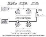
Jumper Length Image

Look what I found. Not exactly the same device, but the dimensions do make sense and I believe the concept is valid. It would have been nice if they said where the dimensions are from/to; center of the T, tip of the connector, base of the connector, etc.
 

Attachments

  • Duplexer jumper lengths 1.jpg
    Duplexer jumper lengths 1.jpg
    56.6 KB · Views: 2,434

902

Member
Joined
Nov 7, 2003
Messages
2,625
Location
Downsouthsomewhere
Thank you, Jim!

Include with that, the amount of length the coupling loop contributes to the length. These were for the Bird cans. I roughly have a quarter wave with the velocity factor and some fudge factor for the internals of each can. The cables are actually a little longer than what a FB friend indicated from a factory-bought 2 meter duplexer, which is probably okay because I'm in the lower portion of the band. The only thing I don't have is the 1/2 wave segments between the T connector and the ending cavity, which didn't seem to be part of the factory spec - not that anyone really knows what that is, and Kit Parsons seems to have taken that to the grave with him. I'm going to have to try that at some point and realign the whole thing (again). I've got a Z-matcher on the transmitter to make nice between the Bridgecom repeater's TX brick and the input cavity. The TX cable length in this duplexer is very critical and the Z-match helps quite a bit.

I'm trying to figure out how to attach a photo without uploading it to another place (I don't really have anywhere to upload it to). My luck's been really bad on this project. The odd split actually gave me a mixing product where my transmitter was getting back into my receiver. I also still couldn't get rid of the desense with the cans flipped so they were no longer on the "buffed out" sections of the plunger, and the additional isolation from a wider frequency split. At the moment, I'm back to 600 kHz.

Contacted another RR member who is kind of local to me. Hopefully he can give this thing the last shot on a Rhode and Schwarz VNA. I'm also going to start looking at my antenna and transmission line characteristics, as it all seems to work on a dummy load. Worst case, I'll put the whole system up for sale and we'll go back to 6 meter simplex :D
 

jeatock

Member
Premium Subscriber
Joined
Jul 9, 2003
Messages
599
Location
090-45-50 W, 39-43-22 N
Something that has been forgotten. Feet of elevation times wattage equals miles. Never pin drop clear perfect, but always solid and usable for those of us who do not consider a hint of noise to be totally unreadable.
 

WA0CBW

Member
Premium Subscriber
Joined
Dec 8, 2011
Messages
1,635
Location
Shawnee Kansas (Kansas City)
"jeatock" -- The length of the cables is somewhat determined by the connectors. Make the jumper length as if the connector wasn't there. Example of a PL259/SO239 is the pin on the 259 slips inside 239. The portion of the center pin that slips into the 239 is part of the 239 so the cable length would be less the length of center pin. Think of it as just butting two pieces of coax together. So it depends on the type of connector as to the actual length of mating parts.
BB
 

jeatock

Member
Premium Subscriber
Joined
Jul 9, 2003
Messages
599
Location
090-45-50 W, 39-43-22 N
Exactly.

The mysterious and unknown internal parts add to the electrical length, plus I switched the broken UHF "T" to a N-style to mate into the antenna system. At least I had the old RG8 (yes, RG8) water-logged jumpers to give me a start; 902 didn't. My can jumpers ended up at 12~14 inches of RG142 (I'm at home and don't remember), a far cry from the ~19" theoretical quarter wave. My other issue was that the filters originally came from a 160-something system and I tuned them for a 145M -600K split, knowing I needed longer jumpers.

The drawing I attached gives theoretical dimensions, but fails to say where the dimensions are anchored. It is sort of like telling an old machinist to drill two holes in a plate and handing him a 600-page doctoral thesis on hole theory instead of simply defining hole diameter and center-to-center spacing. That's the difference between scientists and engineers, and actual manufacturing.

The old machinist will toss the 600-page doctoral thesis and make a part that works. That's pretty much what I ended up doing. I did dumb trial and error on the TX side until I thought the throughput was acceptable then mirrored the dimensions to the low RX side, plus/minus a smidge.
 
Last edited:
Status
Not open for further replies.
Top