AH-703 Counterpoise

Status
Not open for further replies.

boochk

Member
Joined
Feb 22, 2008
Messages
23
Location
Niceville, Florida (Bluewater Bay)
I purchased an AH-703 Antenna at the Huntsville Hamfest but did not include the factory counterpoise wire. Can someone please let me know the length Icom used for this wire? I understand there are two wires of the same length.

Thanks,
John
N4WII
 

vagrant

ker-muhj-uhn
Premium Subscriber
Joined
Nov 19, 2005
Messages
3,177
Location
California
I just measured them and each wire is around 16 feet in length (5 meters each) which makes sense. Alternatively, you could have one long wire 10 meters in length and just wind it up as you climb up the bands. Keep it elevated and you'll notice a difference versus it laying on the ground.

I do this with my Buddipole too when putting it into a vertical configuration. I measured out the 1/4 wave lengths and marked them with tape. I use a long nylon/plastic stake to hold the end up off of the ground. I could just configure the Buddipole into an L configuration, but it's about having fun and experimenting as the locations from where I transmit are always changing.

Hmm...this has me thinking and it would be interesting to try two of the AH-703 antennas in a dipole configuration. I would be better off configuring the Buddipole as a dipole, but again it is about experimenting and having fun.

Anyways, if you're going to join two 5 meter long wires like the original that came with the antenna, make another set and test again and again at different locations with two and then all four wires pointing in different directions.
 

boochk

Member
Joined
Feb 22, 2008
Messages
23
Location
Niceville, Florida (Bluewater Bay)
Vagrant,

Thank you for the length and advice. When I purchased the antenna, I found a tripod at another booth made by Blue Star. It has a UHF barrel connector in the center and makes a nice mount for the antenna. Like you, I like to experiment with my gear. I have the IC-703+ and an FT-817 and plan to try out the antenna soon. I bought a spool of 18Ga. wire and plan on trying some different lengths.

Regards,
John
N4WII
 

Kb2Jpd

Member
Joined
May 6, 2016
Messages
207
Location
New York City, NY
If you are going to use it, you should just get a hamstick for the lowest band you will be operating. Then use that as your counterpoise.


Sent from my iPhone using Tapatalk
 

prcguy

Member
Joined
Jun 30, 2006
Messages
15,349
Location
So Cal - Richardson, TX - Tewksbury, MA
A single counterpoise element is very different than multiple, equal length counterpoise wires or a ground plane. If you take a single vertical element and add a single resonant or non resonant elevated counterpoise wire, you made an inverted V dipole on its side with one element usually low and parallel to the ground. The single Hamstick counterpoise or the single wire used with a vertical Buddistick are classic examples.

If the single elevated counterpoise wire is not 1/4 or multiple of 1/4 wavelength then the feedline will also become a dipole antenna element and will radiate. If the single counterpoise wire is laying on the ground, its no longer resonant and will incur additional ground loss making the overall antenna less efficient. If your going to only use one counterpoise then treat it like a dipole element and get it up in the air.

For two or more counterpoise wires, resonant length or not, if they are equal lengths the RF currents traveling in equal and opposite directions on the radials will cancel radiation leaving only the vertical element to radiate. If the multiple counterpoise radials are elevated and there are only a few like three or four its nice to have them a resonant 1/4 wavelength. Laying them on the ground will detune them and cause the same problem with ground loss as above.
prcguy


If you are going to use it, you should just get a hamstick for the lowest band you will be operating. Then use that as your counterpoise.


Sent from my iPhone using Tapatalk
 

Kb2Jpd

Member
Joined
May 6, 2016
Messages
207
Location
New York City, NY
Here is the PDF. Notice there is no discussion of counterpoise just grounding wires to the Ic,703.

http://www.thiecom.de/ftp/icom/ah703/ah-703.pdf


Sent from my iPhone using Tapatalk


The document describes the antenna as self-resonant and should not need a counterpoise. However, it does recommend changing the separation cable for best SWR.

Prior experience agrees with that. It is a very well built antenna designed for physical abuse, as it was made for a backpack.


Sent from my iPhone using Tapatalk
 

boochk

Member
Joined
Feb 22, 2008
Messages
23
Location
Niceville, Florida (Bluewater Bay)
Vagrant and Prcguy,

Thank you for your insightful comments. I have not had time to play with the AH-703 but has me doing some reading on the subject. I have a Buddipole and a couple of Buddisticks along with various other homemade antennas. I purchased the AH-703 antennas as one of the few options I do not have for my IC-703Plus. Although it was used to connect directly to the rear of the radio, this seems impractical as the counterpoise just routes outside the side pockets of the backpack and onto the ground. It turns out the antenna is made by Diamond as model RHV5. I have been unable to locate any paperwork on the Diamond antenna. As I was reading through the low band portion of the Buddiepole, I noticed they recommend keeping the counterpoise off the ground as well. I have never raised the counterpoise off the ground in the past but it is obvious in reading your posts along with other documentation as to why.

Years ago, I came across a LAPP insulator that was perfect for making a ground plain antenna for HF. I fit in the center a ¾” conduit which I cut for 10 Meters. I then slit the end of the conduit and fed a ½” conduit down the center and marked the 15 and 20 Meter resonance points and tightened it with a hose clamp. I then mounted it on a metal base and had a friend weld 3 pieces of rebar to the bottom of the plate so it could be secured to the ground with a hammer. Last I cut 2 counterpoise wires for 10, 15, 20, and 40 meters and circulated them from the base in a circular pattern around the antenna. I just used tent stakes at the end of each wire to stake them to the ground. It works well in an open field but never worked well around my home. I am curious if I had elevated the counterpoise if it would have worked better. Last, I have reviewed a few websites on ground plane antennas and noticed they all cut the counterpoise the same length as the vertical. I thought you always added 5% on the counterpoise. I know if you use a balun that is not necessary but am confused. On the higher frequencies you can bend the counterpoise down to get a better match for 50 ohms. I assume that’s why you need a 4:1 balun on lower frequencies.

I know I have wandered a bit off topic but am interested in your thoughts.

Thanks,
John
N4WII
 

prcguy

Member
Joined
Jun 30, 2006
Messages
15,349
Location
So Cal - Richardson, TX - Tewksbury, MA
If a ground plane is a full 1/4 wavelength then it makes sense the ground radials would be the same length because that is the best length for a small number of radials above ground. Otherwise most of the current in ground radials is closer to the feedpoint and if you cant have several radials 1/4 wavelength long then use a lot of shorter ones and the more the better. Or use a couple of 3 or 4ft wide lengths of metal hardware cloth or chicken wire as a ground plane, which has a lot of surface area and can replace a whole lot of wire radials.

If you stick a full 1/4 wavelength vertical radiator over a huge copper sheet (think several acres) the feedpoint impedance at resonance would be lower than 50 ohms and somewhere around 35 ohms. If you reduce the ground plane from a huge sheet of solid metal to three or four 1/4 wavelength elevated radials, the feedpoint impedance goes up closer to 50 ohms. Part of the impedance change is due to less capacitance between the vertical radiator and the ground plane with a few radials vs a large solid sheet of metal.

If you bend the ground radials downward it will raise the impedance some, depending on the angle. If you think about a 1/2 wave dipole in free space, it has a feedpoint impedance around 70-72 ohms. That would be an extreme example of bending ground plane radials all the way down until they are inline with the vertical radiator but pointing the opposite direction. Bend them up from a dipole type scenario to sticking out 90deg from the vertical and you can cover a range from about 70 to 50 ohms or so. Antenna height above ground will also influence things.

When you shorten a vertical antenna via loading coils it lowers the feedpoint impedance and the shorter the antenna is in wavelengths, the lower the impedance. If you were to shorten say a 33ft 1/4 wavelength 40m vertical over an effective ground plane to 6ft long with a loading coil, the feedpoint impedance would be very low, probably around 12-15 ohms.

I don't know why you would use a 4:1 balun on a ground plane, especially a shortened one except under extreme conditions like using a 43ft vertical to cover the entire HF band, which is done but its not a very good idea. On 160 through 80m the feedpoint of a 43ft vertical is much lower than 50 ohms but the 4:1 balun has a 200 ohm connection to the antenna and a lot of loss on the lower bands. On a few bands is probably an OK compromise and above about 17m the radiation pattern of a 43ft vertical is so bad its not really usable. In the case of a 4:1 balun on a 43ft vertical it sort of makes the match seem better at the cost of lots of loss but it allows the mfrs to advertise the antenna as having a reasonable match everywhere so they can sell antennas. Hope some of my rambling answered a few questions.
prcguy


Vagrant and Prcguy,

Thank you for your insightful comments. I have not had time to play with the AH-703 but has me doing some reading on the subject. I have a Buddipole and a couple of Buddisticks along with various other homemade antennas. I purchased the AH-703 antennas as one of the few options I do not have for my IC-703Plus. Although it was used to connect directly to the rear of the radio, this seems impractical as the counterpoise just routes outside the side pockets of the backpack and onto the ground. It turns out the antenna is made by Diamond as model RHV5. I have been unable to locate any paperwork on the Diamond antenna. As I was reading through the low band portion of the Buddiepole, I noticed they recommend keeping the counterpoise off the ground as well. I have never raised the counterpoise off the ground in the past but it is obvious in reading your posts along with other documentation as to why.

Years ago, I came across a LAPP insulator that was perfect for making a ground plain antenna for HF. I fit in the center a ¾” conduit which I cut for 10 Meters. I then slit the end of the conduit and fed a ½” conduit down the center and marked the 15 and 20 Meter resonance points and tightened it with a hose clamp. I then mounted it on a metal base and had a friend weld 3 pieces of rebar to the bottom of the plate so it could be secured to the ground with a hammer. Last I cut 2 counterpoise wires for 10, 15, 20, and 40 meters and circulated them from the base in a circular pattern around the antenna. I just used tent stakes at the end of each wire to stake them to the ground. It works well in an open field but never worked well around my home. I am curious if I had elevated the counterpoise if it would have worked better. Last, I have reviewed a few websites on ground plane antennas and noticed they all cut the counterpoise the same length as the vertical. I thought you always added 5% on the counterpoise. I know if you use a balun that is not necessary but am confused. On the higher frequencies you can bend the counterpoise down to get a better match for 50 ohms. I assume that’s why you need a 4:1 balun on lower frequencies.

I know I have wandered a bit off topic but am interested in your thoughts.

Thanks,
John
N4WII
 
Last edited:

boochk

Member
Joined
Feb 22, 2008
Messages
23
Location
Niceville, Florida (Bluewater Bay)
PRCGUY,

After reviewing your post and my thoughts, I realized I was unclear on several of my comments; however, you did answer my questions. I have never used a balun on a ground plane antenna but on 80 and 40 meter verticals and dipoles, I have used my 4:1 Buddipole balun to match the lower impedence. At 4:1 the balun goes from 50 to 12.5 Ohms and matches much better on my transceiver.

Back in the 80’s I worked for a small company called Aerocom and possessed far more knowledge on electronics. Since leaving the field, I have forgotten much of my past knowledge and find this discussion refreshing. Aerocom manufactured ground based aviation transceivers including NDBs. All of the NDB’s had an output impedance of 10 Ohms since they used large coils at the base of the antenna. I recall they used top hats or “T” antennas to add capacitance to the antennas. Now I remember why.

I purchased a 500’ spool of 18Ga. wire and have some plastic tent stakes to make some counterpoise wires for the AH-703 antenna. The Blue Star mount I bought when I purchased the antenna is small and will have the base of the antenna just over a foot or so above the ground. I will start with 2, 16 foot lengths and try extending the lengths to see what works best. I also have a couple mobile multiband HF verticals I may try as well. Now if I can just find the time for the antenna setup.

I still have some questions but will do some more reading before post anything further. Thank you to everyone for their knowledge sharing.

John
N4WII
 

prcguy

Member
Joined
Jun 30, 2006
Messages
15,349
Location
So Cal - Richardson, TX - Tewksbury, MA
Ok on the Buddipole balun, its 50 ohms to 12.5 ohms and correct for what you are doing. Most 4:1 baluns are used as 50 to 200 ohm and I see a lot of people using those incorrectly on a shortened antenna. Probably the most common is the LDG tuners and 4:1 balun used with a short length of wire on 40 or 80m, not so good.
prcguy


PRCGUY,

After reviewing your post and my thoughts, I realized I was unclear on several of my comments; however, you did answer my questions. I have never used a balun on a ground plane antenna but on 80 and 40 meter verticals and dipoles, I have used my 4:1 Buddipole balun to match the lower impedence. At 4:1 the balun goes from 50 to 12.5 Ohms and matches much better on my transceiver.

Back in the 80’s I worked for a small company called Aerocom and possessed far more knowledge on electronics. Since leaving the field, I have forgotten much of my past knowledge and find this discussion refreshing. Aerocom manufactured ground based aviation transceivers including NDBs. All of the NDB’s had an output impedance of 10 Ohms since they used large coils at the base of the antenna. I recall they used top hats or “T” antennas to add capacitance to the antennas. Now I remember why.

I purchased a 500’ spool of 18Ga. wire and have some plastic tent stakes to make some counterpoise wires for the AH-703 antenna. The Blue Star mount I bought when I purchased the antenna is small and will have the base of the antenna just over a foot or so above the ground. I will start with 2, 16 foot lengths and try extending the lengths to see what works best. I also have a couple mobile multiband HF verticals I may try as well. Now if I can just find the time for the antenna setup.

I still have some questions but will do some more reading before post anything further. Thank you to everyone for their knowledge sharing.

John
N4WII
 

boochk

Member
Joined
Feb 22, 2008
Messages
23
Location
Niceville, Florida (Bluewater Bay)
PRCGUY,

Your last comments have had me thinking a lot about baluns. I never put much thought into the subject but you switched on a light. I have one of those LDG baluns and knew it was 50 to 200 ohms. I also knew that the Buddipole balun was switchable down in impedance but never made the connection that they were named the same. After some reading, there does not seem to be a standard term for each to differentiate them.

Other than Buddipole, I am unable to locate a source to buy a 300 watt or less balun for 50 to 12 ohms. Do you know of anyone else selling them? If not, can you point me to a kit or parts list to make one? From what I have read so far, the only ones that are practical use 2 cores, although I seem to recall the one for my Buddipole only had one.

I have a UVH-6 made by Comet and it has coils for 40 an 80 Meters. The feedpoint must be very low as well. I used it when I had my FT-857 in my car. I am wondering how they maintain the impedance for those lower bands without matching. I am guessing they must add capacitance to the base. Any thoughts?

After considerable reading, I think after I am done with the AH-703 and the other antennas, I may try and build an off center dipole and put that LDG balun to use. I am getting lots of ideas for winter projects.

I know I have wandered off topic again but since we have discussed this a little, thought I would continue here. I can create a new topic if you prefer.

Regards,
John
N4WII
 

prcguy

Member
Joined
Jun 30, 2006
Messages
15,349
Location
So Cal - Richardson, TX - Tewksbury, MA
I don't have any specific plans for a 50 to 12.5 ohm balun/unun, etc, but here is a 50 to 20 ohm project, which is a good compromise for an 80 through 10m shortened vertical like the buddistick. Its good for at least a couple hundred watts and will match 80 and 40m fairly well without compromising the upper most HF bands where you probably don't need to transform the impedance down much from 50 ohms. I've made one of these and they work fine and only cost a few $$. broadband mobile HF matching xfmr de N6CA

Some mobile HF antennas have loading coils made of very small wire and are very lossy, plus they have poor mounting schemes that introduce ground losses, which raises the feedpoint impedance and provides a better match at the cost of poor performance. The Yaesu ATS series is a good example of this and the Comet UVH-6 might be in the same boat.

I made a portable 80-10m offset center fed dipole for travel that works great and constantly surprises me with its performance. The key is the great 4:1 current balun I copied from Elecraft that is made on a very small binocular ferrite core and seems to have good common mode rejection to keep RF off the coax. Here are the plans for the balun: http://www.elecraft.com/manual/E740061 BL1 4 to 1 Rev B.pdf and the ferrite core is a BN43-7051 available here: BN-43-7051 - Amidon

I used #22 Teflon wire to wind the 4:1 balun but you can strip a twisted pair from CAT5 cable and use that since its insulation is good for a fairly high frequency. I believe an offset ratio of 19% and 81% is best and the exact length will depend on the wire you use but overall length will be close to 133ft for insulated wire. You might make one several feet longer than 133ft using the 19/81% formula, then trim each side equally to get the best match on 40 and 20m, then it should be good to go on most HF bands. I used #22 wire for the antenna to keep it lightweight for portable use.

My absolute favorite portable antenna for 40-10m is a resonant half wave end fed that is 63ft long and winds up into a plastic chalk line reel with about 40ft of guy string. Its a great performer and very lightweight and portable and a good match for my KX3 and KX2. I'll post info on that if your interested.
prcguy

PRCGUY,

Your last comments have had me thinking a lot about baluns. I never put much thought into the subject but you switched on a light. I have one of those LDG baluns and knew it was 50 to 200 ohms. I also knew that the Buddipole balun was switchable down in impedance but never made the connection that they were named the same. After some reading, there does not seem to be a standard term for each to differentiate them.

Other than Buddipole, I am unable to locate a source to buy a 300 watt or less balun for 50 to 12 ohms. Do you know of anyone else selling them? If not, can you point me to a kit or parts list to make one? From what I have read so far, the only ones that are practical use 2 cores, although I seem to recall the one for my Buddipole only had one.

I have a UVH-6 made by Comet and it has coils for 40 an 80 Meters. The feedpoint must be very low as well. I used it when I had my FT-857 in my car. I am wondering how they maintain the impedance for those lower bands without matching. I am guessing they must add capacitance to the base. Any thoughts?

After considerable reading, I think after I am done with the AH-703 and the other antennas, I may try and build an off center dipole and put that LDG balun to use. I am getting lots of ideas for winter projects.

I know I have wandered off topic again but since we have discussed this a little, thought I would continue here. I can create a new topic if you prefer.

Regards,
John
N4WII
 

boochk

Member
Joined
Feb 22, 2008
Messages
23
Location
Niceville, Florida (Bluewater Bay)
PRCGUY,

Thanks again for the wealth of information and help! I am putting together a shopping list to build the balun/unun in the N6CA link you provided. It looks easy enough to build and should easily fit into some PVC tubing. Hopefully by the time the items arrive, I will be done with some household chores.

As I have been pouring over Google and different information, I stumbled across an MFJ-907. According to what I have read, it too is a matching transformer with taps. Not much to read on reviews but may be worth tinkering with. They claim it will handle 1KW. Overkill for my QRP stuff.

When you have time, yes I would be interested in the long wire antenna. Is it difficult to deploy? does it sag in the middle? How high off the ground do you use it? I have lots of cat 5 stuff thanks to my work, mostly patch cables but might be able to locate a short spool of cat5 plant cable.

When I do get around to testing my AH-703, I may try to examine if it has the loading coil along with my other mobile antennas. I even have a Kenwood MA-5 antenna. Found it in a parts bin and didn't even know what it was. My original plan was to mimic the original Icom counterpoise but may use 4 wires instead of two. I have the Icom backpack and at some point, may run over to Destin and give it a try. Europe used to boom in over there in the afternoon on 40 Meters when I would take my son to soccer. Since he is starting collage, I am finding more time for my radio stuff. I miss Aerocom....

Regards,
John
N4WII
 

prcguy

Member
Joined
Jun 30, 2006
Messages
15,349
Location
So Cal - Richardson, TX - Tewksbury, MA
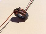
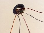
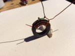
Here are some plans for my favorite portable HF antenna, a resonant end fed half wave. I use an FT-114A-43 ferrite toroid (about $2 from Amidon) for a 100w version and you wind it exactly like the links with 2 turns of twisted pair for the primary and 14 turns for the secondary. I usually cross over the secondary after 7 turns as in the links but I haven't noticed any difference just doing 14 turns in a row.

PD7MAA HOMEPAGE: Multiband end fed antennas 3.5 - 30mHz

https://pa3hho.wordpress.com/end-fed-antennes/multiany-band-end-fed-english/

You will also need a 100 to 150pf capacitor across the input and I use dipped silver micas rated at 500v. Otherwise forget about any loading coil mentioned in the links and cut about 65ft of wire and trim for the best match at the low end of 40m and it will cover 40, 20, 15 and 10m without a tuner.

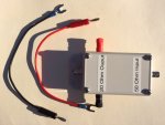
I also use a common mode choke and the miniature coax in the picture has about 5 turns through a large #31 ferrite bead near the radio end. The picture shows a complete 100w version with about 63ft of #22 Teflon wire and about 40ft of miniature parachute cord wound up in a plastic chalk line reel. There is a Zippo lighter next to it for size comparison and also a large dual core version that handles up to about 800w.

To use the antenna you connect the lug on the wire to the transformer box, spool out all the wire and string, then the empty chalk line reel is the throw weight to get the string side of the antenna up into a tree or whatever. Since the wire and string are very light weight it doesn't take much tension to keep the wire straight and taut.

This antenna completely kicks butt over a Buddipole, Buddistick or anything similar and it probably cost under $20 to build not including coax. If you were to feed a 40m 1/2 wave dipole with ladder line you would get the exact same radiation pattern and performance as this antenna on the bands its tuned for and you can put 1/2 wavelength of wire for 17m or 60m or any frequency and the transformer will make it work.

I usually use RG-316 miniature Teflon coax or LMR-100, both are the same size as RG-174. I use this antenna horizontal between 10 and 20ft off the ground or as a sloper with the far end as high as I can get it and the transformer near the radio.
prcguy

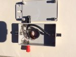
Edit: If you make one take a look at my smaller black transformer box and how the wing nut output stud is on the side of the box 90deg from the line of pull. This works good and if you put the output screw/stud in line with the antenna wire it will bend and weaken the lug on the antenna wire. I also have the eye ring for tying off the transformer in line with the antenna output and this puts the eye bolt in a corner of the box where its stronger and less likely to break the box apart.


PRCGUY,

Thanks again for the wealth of information and help! I am putting together a shopping list to build the balun/unun in the N6CA link you provided. It looks easy enough to build and should easily fit into some PVC tubing. Hopefully by the time the items arrive, I will be done with some household chores.

As I have been pouring over Google and different information, I stumbled across an MFJ-907. According to what I have read, it too is a matching transformer with taps. Not much to read on reviews but may be worth tinkering with. They claim it will handle 1KW. Overkill for my QRP stuff.

When you have time, yes I would be interested in the long wire antenna. Is it difficult to deploy? does it sag in the middle? How high off the ground do you use it? I have lots of cat 5 stuff thanks to my work, mostly patch cables but might be able to locate a short spool of cat5 plant cable.

When I do get around to testing my AH-703, I may try to examine if it has the loading coil along with my other mobile antennas. I even have a Kenwood MA-5 antenna. Found it in a parts bin and didn't even know what it was. My original plan was to mimic the original Icom counterpoise but may use 4 wires instead of two. I have the Icom backpack and at some point, may run over to Destin and give it a try. Europe used to boom in over there in the afternoon on 40 Meters when I would take my son to soccer. Since he is starting collage, I am finding more time for my radio stuff. I miss Aerocom....

Regards,
John
N4WII
 

Attachments

  • end feds.jpg
    end feds.jpg
    109.4 KB · Views: 1,019
Last edited:

boochk

Member
Joined
Feb 22, 2008
Messages
23
Location
Niceville, Florida (Bluewater Bay)
PRCGUY,

That is a nice setup and looks easier than the Buddipole or the Buddistick to setup. I may add that to the growing list of projects this winter.

Over the weekend I had some time to work with the AH-703 antenna. I placed the antenna on the Blue Star mount as high as I could on the mount (Legs closest together) and placed the mount on the ground. Then I cut 4 18Ga. counterpoise wires roughly 16.5’ around the antenna supported off the ground with plastic tent stakes. I connected the antenna to my FT-817 and adjusted the whip to the lowest SWR on the 817. I was able to adjust it so there was no SWR meter indication at 5 Watts on 20 Meters. I then spoke with W1CTN in Connecticut, he gave me a 5/3 report. Not bad from the Florida Panhandle on 5 Watts. Because the California contest was this weekend I didn’t try to make any further contacts. Without changing the counterpoise, I then adjusted the antenna for 40 and 10 Meters. I could get the SWR acceptable but without adjusting the counterpoise was unable to get the same results as on 20 Meters but that was expected. I ran out of time to go any further but am satisfied with my results so far. Hopefully I will have time to adjust the counterpoise lengths next weekend. I also checked with an ohmmeter if there was a loading coil. I measured an open from the center conductor to ground. The MA-5 and my UHV-6 are open as well.

I have ordered 4 toroid cores (FT-114-61) from the N6CA plans and enough wire for the project. All I need now is some PVC pipe and ends.

Thanks,
John
N4WII
 

boochk

Member
Joined
Feb 22, 2008
Messages
23
Location
Niceville, Florida (Bluewater Bay)
Update:

I have not received all of the items ordered but thought I would share my progress. I purchased 3 different color wires to make it easier to identify the windings. I don't know how important it is to wind the wires tight around the toroid but made them as tight as I could. This project looks easy but is a bit more difficult than it looks. The pictures are my second attempt as the first one I was unhappy with. I have enough material for 4 baluns and after I finish this one, will build the others to see if I can improve my results.

John
N4WII
 

Attachments

  • IMG_0396.JPG
    IMG_0396.JPG
    71 KB · Views: 1,008
  • IMG_0397.JPG
    IMG_0397.JPG
    72.5 KB · Views: 885
  • IMG_0398.JPG
    IMG_0398.JPG
    66.5 KB · Views: 983

prcguy

Member
Joined
Jun 30, 2006
Messages
15,349
Location
So Cal - Richardson, TX - Tewksbury, MA
Your balun looks like a commercial made one, congratulations. When winding something like this I like to get the first turn on, then push the remaining turns through as loops coming off the previous turns and pulling the wire through the core rather than threading the turns like a needle through the hole with the very end of the wire. This makes for tighter turns on the core and less lumps in the wire.
prcguy

Update:

I have not received all of the items ordered but thought I would share my progress. I purchased 3 different color wires to make it easier to identify the windings. I don't know how important it is to wind the wires tight around the toroid but made them as tight as I could. This project looks easy but is a bit more difficult than it looks. The pictures are my second attempt as the first one I was unhappy with. I have enough material for 4 baluns and after I finish this one, will build the others to see if I can improve my results.

John
N4WII
 

boochk

Member
Joined
Feb 22, 2008
Messages
23
Location
Niceville, Florida (Bluewater Bay)
PRCGUY,

Thank you for the link to the N6CA Balun. I completed the project yesterday with impressive results. The lower bands where I have had low impedance mismatches are much more manageable. In the past, I have used the Buddipole balun but found this is a good compromise for the Hamsticks. I used a Rigexpert antenna analyzer to test the various bands and have more useable bandwidth rather then having to retune the antenna for minor frequency changes. For the output, I used binding posts and a BNC connector for flexibility. In the end I only built two baluns but have enough materials to build two more.

By the way, I used bent nose pliers with masking tape on the ends to get the wires tight around the core without stripping the enamel off the wire. I had not thought about running the next windings through the core but am pleased with the end result.

John
N4WII
 

Attachments

  • IMG_0415.JPG
    IMG_0415.JPG
    78.2 KB · Views: 691
  • IMG_0418.JPG
    IMG_0418.JPG
    89.1 KB · Views: 897
  • IMG_0419.JPG
    IMG_0419.JPG
    115 KB · Views: 903

prcguy

Member
Joined
Jun 30, 2006
Messages
15,349
Location
So Cal - Richardson, TX - Tewksbury, MA
Looks great and a good way to help match a shortened whip or dipole. Plus the transformer will probably handle more power than a Buddipole. Chip is a very smart guy and when I was making one of the transformers he said it should handle my 500w mobile amp.

One thing I would do add a common mode choke between the transformer and your feedline since the transformer probably doesn't have much common mode rejection. You can make an effective choke with about 10 turns of minature coax like RG-174 or RG-315 Teflon around a small enough core to fit inside your existing box. An FT-140-31 or -43 core should be fine or an FT-114A-31 is the same diameter as the transformer and should have usable choking impedance down to 40M.
prcguy

PRCGUY,

Thank you for the link to the N6CA Balun. I completed the project yesterday with impressive results. The lower bands where I have had low impedance mismatches are much more manageable. In the past, I have used the Buddipole balun but found this is a good compromise for the Hamsticks. I used a Rigexpert antenna analyzer to test the various bands and have more useable bandwidth rather then having to retune the antenna for minor frequency changes. For the output, I used binding posts and a BNC connector for flexibility. In the end I only built two baluns but have enough materials to build two more.

By the way, I used bent nose pliers with masking tape on the ends to get the wires tight around the core without stripping the enamel off the wire. I had not thought about running the next windings through the core but am pleased with the end result.

John
N4WII
 
Status
Not open for further replies.
Top