Receiving distance with rinky dink SDR Antenna?

Status
Not open for further replies.

humblegeo

Member
Premium Subscriber
Joined
Jan 5, 2017
Messages
233
Location
Humble, Texas
I live about 10 miles from Bush Intercontinental Airport in the Houston Tx area. It looks like with virtual radar server I'm dropping out at about 6 or 7 miles from my location. Is this about right for the rinky dink antenna that comes with the SDR?

P.S. After rechecking several times It's really dropping out more like about 4 miles from my location.
 
Last edited:

rbm

Member
Joined
Jan 25, 2005
Messages
1,395
Location
Upstate New York
I'm surprised that you're even doing that well! ;)

When I tried that antenna with the first USB Dongle I got years ago, I thought the dongle was DOA!

I couldn't even receive the local NOAA weather broadcast about 8 miles from me.

Although, make sure you have your RF gain set somewhere around 20dB to start.
I don't know why they default to zero!

Here's what the dongle can do with a good antenna.
UHF SatCom
https://www.youtube.com/watch?v=GzQWGPzs1r8

Rich
 

humblegeo

Member
Premium Subscriber
Joined
Jan 5, 2017
Messages
233
Location
Humble, Texas
WOW!! You've got me motivated to build my own antenna now. I just recently ordered from ebay a $5.00 6" RF coaxial cable assembly MCX Male Right Angle to BNC Female Bulkhead with the intentions of trying out the telescopic antenna I'm using on my PRO-668 or I've got another telescopic on a Uniden BC355N that I could try but I like your idea better. I need to look into what a SO-239 chassis mount connector is and figure out what length the antenna needs to be for the 127 Mhz. Maybe about 2 feet.

Thanks again for the education and ideas for a diy antenna to replace the rinky dink garbage that I am currently using.

Larry G
 

rbm

Member
Joined
Jan 25, 2005
Messages
1,395
Location
Upstate New York
And ..... now that you have the dongle, here's something to think about.
(A great way to drain your cell phone battery! ;) )

Take it with you!


Rich
 

Dog

Member
Joined
Jun 3, 2003
Messages
396
Location
Oklahoma
I live about 10 miles from Bush Intercontinental Airport in the Houston Tx area. It looks like I'm dropping out at about 6 or 7 miles from my location. Is this about right for the rinky dink antenna that comes with the SDR?

I think you are using VRS. Go to Tools, Options, Web Server, check "Internet users can see receiver range plots", then on the web page menu, you should have an try "Range Receiver" click that, check "All Altitudes". Now you can click the different altitudes and see what you antenna is doing. You won't see a lot under 9,999', see more at 10,000 to 19,999, etc.

Now click menu, Options, Map tab, Under "Range Circles", check the box next to "Show range circles". Below that you can change the distance, quantity, color of the circles.

All this will give you a good idea of your antennas performance.

There are a lot of options to make what you have better. However HEIGHT get you better no matter what antenna you use.

I started with the stock antenna. 1090 mhz quarter wave is 69 mm. You can cut the stock whip down to 69 mm. That helps some but not much in my experience.

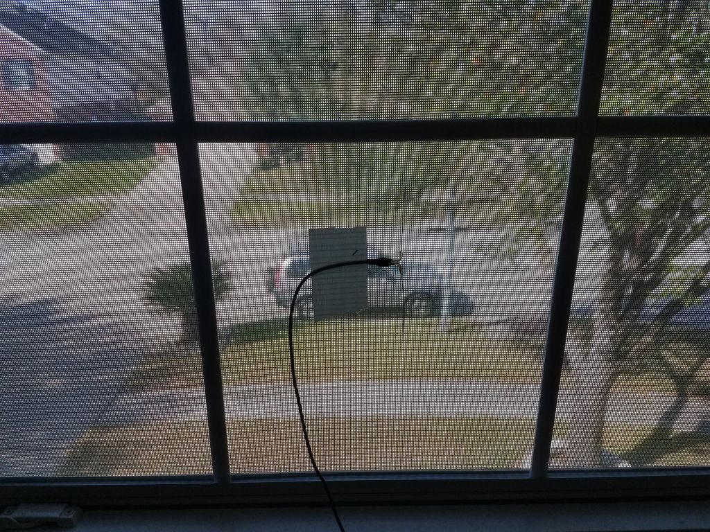
Next I took the bottom off the stock antenna and cut the wire to pull the coax out. I cut the outside sheath back 69 mm, then separated the inner conductor from the outer braid, and made a half wave dipole that I taped outside the glass window. It was only 6 or so feet above the ground but it did amazing for what it was. 40 mile radius on house side 60 mile radius on antenna side.

Like this https://www.youtube.com/watch?v=ffWmr6p0dho

The I built a quarter wave ground plane (cheap and very easy to build) it is at 8 feet above the ground and I get 80 to 100 mile radius.

My next step is getting it up above the ridge line of the house.

Warning it gets addicting.
 
Last edited:

humblegeo

Member
Premium Subscriber
Joined
Jan 5, 2017
Messages
233
Location
Humble, Texas
My setup is upstairs so I'm already probably 12-15 ft above ground, although indoors. I'll play with VRS as you suggested and see my distance with the little antenna that came with the SDR but I know from what everyone has said that it's got to go or be modified.

Thanks for the help
Larry G
 

humblegeo

Member
Premium Subscriber
Joined
Jan 5, 2017
Messages
233
Location
Humble, Texas
Dog, what overall length would I need for 127 mhz. You said to do 137 mm overall length on the two pieces for 1090 MHz but I'm thinking that may be the UK standard where as 127 MHz here in the US falls in the middle of the air band. Is that right or am I way off in left field somewhere again?

All I could find were brass rods but I'm thinking it should work about as well as copper rods copper wire.

Appreciate it
Larry G
 

br0adband

Member
Joined
Apr 8, 2005
Messages
1,567
Location
Springfield MO
Use this or most any other 1/4 wave antenna length calculator:

Amateur Quarter Wave Ground Plane Antenna Calculator

For 127 MHz you're looking at a main vertical element length of 22.1 inches (56.2 centimeters for those not using the Imperial system) and if you make a ground plane use 23-24 inches for those radial elements - while it's not absolutely critical I and some other people recommend you give the ground plane elements just a slightly longer length than the main element.

And yes you can make a 1090 MHz 1/4 wave ground plane just as easily but most of the time those antennas are just a simple vertical element and not much else which comprises a sleeved dipole whip inside the PVC/plastic/rubberized housing, some have even made them with a collinear design which is slightly more complex but can be useful in some situations.
 

humblegeo

Member
Premium Subscriber
Joined
Jan 5, 2017
Messages
233
Location
Humble, Texas
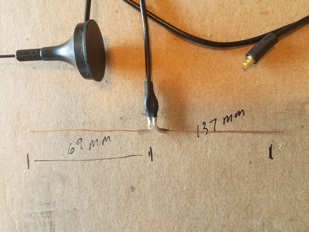
I threw something together here using the cable and rinky dink antenna that came with the sdr. I did get a small improvement in reception but not really that much, Maybe I didn't build it right. I used copper wire single strand and just stripped off the outer insulation. Cut off the little antenna, stripped the antenna wire back some and separated the core conductor from the shield and then soldered seach one to the 2 pre-cut 69 mm copper wire. On RTL1090 the signal strength meter it went from maybe 10 to a intermittent >20. Before the modification I had only a solid >10. I need to play around with the setup and maybe try another build. The screen on the window is not wire mesh type, I think it's like a cloth sun blocking material.


br0adband

Member
Joined
Apr 8, 2005
Messages
1,567
Location
Springfield MO
Yeah, that's the general idea and they're easy to make. That's a dipole design and should work fine, a 1/4 wave ground plane would work just as well, perhaps even a bit better but only building it would prove that presumption. The issue you and many many other people have is that cabling from the rinky dink antenna is crap, plain and simple, as I mentioned above. The primary reason those antennas suck is not the antenna itself but the cabling, it's barely got enough copper in it to call it shielding and basically does nothing more than transmit the signals and not very well at all.

An antenna is just a conductive piece of material at it's most basic purpose, but if you have an antenna and the connection between the antenna and the receiver is crap - as that cabling is - it's going to hurt reception (and if you're transmitting it will waste output power and even cause other problems as well). Since we're only dealing with reception exclusively it's still going to hurt things, the loss that such crappy cable has even affects things at such relatively short lengths, sadly.

Also, I'm not 100% certain of this but that looks like both those leads are touching at the point where they're being "split" apart and bent at the angle - the brass material you're using there to attach the actual wire elements does appear to be in contact and if that's true you're shorting it and that's not good. :)
 

Dog

Member
Joined
Jun 3, 2003
Messages
396
Location
Oklahoma
I threw something together here using the cable and rinky dink antenna that came with the sdr. I did get a small improvement in reception but not really that much, Maybe I didn't build it right. I used copper wire single strand and just stripped off the outer insulation. Cut off the little antenna, stripped the antenna wire back some and separated the core conductor from the shield and then soldered seach one to the 2 pre-cut 69 mm copper wire. On RTL1090 the signal strength meter it went from maybe 10 to a intermittent >20. Before the modification I had only a solid >10. I need to play around with the setup and maybe try another build. The screen on the window is not wire mesh type, I think it's like a cloth sun blocking material.

It is just something to play with while you research and source parts for a proper build, however that is about what to expect.

I would recommend something like this quarter wave ground plane out of a bulkhead connector of your choice and some wire. I used a SO-239 Connector and some 12 gauge copper wire. This is a photo off google images but mine looks similar.


Here is another site with some useful information:
Three Easy DIY Antennas for Beginners : ADS-B Flight Tracking
 

humblegeo

Member
Premium Subscriber
Joined
Jan 5, 2017
Messages
233
Location
Humble, Texas
How do you connect it to your sdr? I think mine is MCX.. I purchased some brass rods today. 1/8 inch x 3 ft. 2 rods. I couldn't find any copper rods. Ordered a SO-239 Female Jack PANEL Mount Adapter today as well.
 

br0adband

Member
Joined
Apr 8, 2005
Messages
1,567
Location
Springfield MO
I build those myself pretty regularly, they're cheap and easy to make, doesn't even require soldering for good/great performance especially if you create one cut to a specific band-center frequency and use it for that dedicated purpose. I have various ones at: 127, 150, 300, 450, 772, 855, and 935 and switch 'em out from time to time as needed.

Been wanting to make myself an adjustable one, actually, from 5 telescopic whip elements that can easily be adjusted as required so it doesn't take up as much space as the others do (they're "stacked" in a box basically and taken out when needed). I keep looking for a good telescopic whip that's not crazy pricing and extends and retracts to the appropriate lengths I require but haven't found a good candidate just yet. It's just another simplistic antenna project but as with all the others even the simple ones can have tremendous benefits at barely any monetary cost at all.

Can't recommend making your own antenna(s) for fun and general experimentation enough.
 

Dog

Member
Joined
Jun 3, 2003
Messages
396
Location
Oklahoma
How do you connect it to your sdr? I think mine is MCX.. I purchased some brass rods today. 1/8 inch x 3 ft. 2 rods. I couldn't find any copper rods. Ordered a SO-239 Female Jack PANEL Mount Adapter today as well.

I have several adapters. MCX to F Type, MCX to BNC, MCX to SO-239, MCX to PL-259, etc. You can get MCX adapters from eBay for $1 but you have to wait on the slow boat from China. You can get them from US shippers but you pay 5 or more times for the same pieces.

The antenna like the one above I use RG6 and f connectors and adapters on both ends. (RG-6 has less loss than most 50 ohm coax at many times its price and works just fine to receive only.)
 

KE5MC

Member
Premium Subscriber
Joined
Dec 19, 2002
Messages
1,235
Location
Lewisville, TX
How do you connect it to your sdr? I think mine is MCX.. I purchased some brass rods today. 1/8 inch x 3 ft. 2 rods. I couldn't find any copper rods. Ordered a SO-239 Female Jack PANEL Mount Adapter today as well.

Romex electrical wiring is a good source. Strip insulation on a length in the three foot range. Place vice grip on one end and lay tool on floor and stand on it. Grab free end of wire with second pair of vice grip. Pull up until you feel the wire increase in length. It doesn't take much, something like 1/2 inch or less. The copper wire will now look like the brass rod you bought. The stretch takes out the kinks.

Mike
 

humblegeo

Member
Premium Subscriber
Joined
Jan 5, 2017
Messages
233
Location
Humble, Texas
Just realized I ordered the wrong thing. Pitiful. I guess I did fall off a turnip truck! I need a so-239 female on one end and the other end is where you solder on the copper rod. I don't need female on both ends. Oh well, maybe I'll find a use for it someday.

UHF adapter SO239 to SO-239 Female jack panel mount adapter straight
*
Product Description:
Category:****************** Connectors, Interconnects
Type:************************* Coaxial, RF Chassis Mount Connector
Series:********************** Chassis Mount*Series
Convert From:********** SO-239 Female
Convert To:************** SO-239 Female
Impedance:************** 50 Ohm
Style:************************ Chassis Mount
Package Includes:
1x UHF adapter SO239 to SO-239 Female jack panel mount adapter straight
 

M105

Member
Joined
Sep 13, 2005
Messages
399
I'll add my 2 cents worth. The SDR Dongles are TV receivers and work well with 75 ohm coax. Don't overlook the myriad of F type chassis mount and other connectors and readily available RG-6 coax. You can also get male and female F to anything adapters and cables pretty cheap. I have made dipoles by simply stripping the shielding from RG-6 and leaving the right length of insulated enter conductor exposed.

The best homebrew antenna I have used and still use today are folded dipoles constructed from 300 to 75 ohm TV baluns. They are very quiet and work well if you are designing for a specific frequency or band. I posted a photo of one of these easy to build antennas a while ago on here. http://forums.radioreference.com/so...ck-not-too-dirty-dipole-idea.html#post2553712

Fun to experiment with.
 
Status
Not open for further replies.
Top