BC780XLT PCB component value

Status
Not open for further replies.

DeDawg

Member
Joined
Mar 26, 2017
Messages
195
Location
Kona, HI
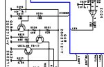
Tracking down a dim display issue, appears the culprit is a blown zener diode in the dimming circuit. Schematic has it's ID as D67, but the value it not readable. Could start soldering in likely values, but that is a bit crude.

Anyone have a component list like what would have come with a factory service manual? It is a SMD part, so might have only one or two chances at replacing it before damaging the PCB. Just the component list would be very valuable to keep this old gem running.
 

Ubbe

Member
Joined
Sep 8, 2006
Messages
9,033
Location
Stockholm, Sweden
Thats controlling the backlight. Is it a dim display or lack of backlight?
Low contrast in the LCD are usually a bad resistor that sits on the display.

/Ubbe
 

pro92b

Mutated Member
Premium Subscriber
Joined
Jun 27, 2002
Messages
1,910
The SMD diode should have a two digit code printed on it. That may help identify the voltage rating.
 

mancow

Member
Database Admin
Joined
Feb 19, 2003
Messages
6,880
Location
N.E. Kansas
The schematic is difficult to read due to being blurry but it appears to indicate VDZ3.0 I can't make out the last character.
 

Attachments

  • dimmer.jpg
    dimmer.jpg
    50.6 KB · Views: 321

pro92b

Mutated Member
Premium Subscriber
Joined
Jun 27, 2002
Messages
1,910
The diode is Rohm UDZ series, available at 3.0, 3.3, 3.6, and 3.9 volts. The printed code on the part should identify which voltage it is.
 

DeDawg

Member
Joined
Mar 26, 2017
Messages
195
Location
Kona, HI
Thats controlling the backlight. Is it a dim display or lack of backlight?
Low contrast in the LCD are usually a bad resistor that sits on the display.

/Ubbe
Very dim, only when OFF is selected. Thread in the archives about this, but no resolution.

Display is good, bringing the emitter of Q601 up momentarily shows good lighting.
 

DeDawg

Member
Joined
Mar 26, 2017
Messages
195
Location
Kona, HI
The diode is Rohm UDZ series, available at 3.0, 3.3, 3.6, and 3.9 volts. The printed code on the part should identify which voltage it is.
Got a datasheet from DigiKey that has Rohm VDZ diodes up to 35 volts. Will try harder to read it now I think I know what the markings should be if Rohm. Schematic does look like 3.**, so not a higher value that 3.9V it appears.
 
Last edited:

pro92b

Mutated Member
Premium Subscriber
Joined
Jun 27, 2002
Messages
1,910
It looks like UDZ on the schematic to me. Here is the datasheet.
 

Attachments

  • UDZ series zener.pdf
    61.5 KB · Views: 69

byndhlptom

Member
Joined
Nov 1, 2005
Messages
399
Location
JoCo, KS (SoDak native)
BCD780 display

You mentioned in another post that you had several 780's. On a working unit, just measure the voltage across the diode, that should be the zener voltage.....

$.02
 

DeDawg

Member
Joined
Mar 26, 2017
Messages
195
Location
Kona, HI
You mentioned in another post that you had several 780's. On a working unit, just measure the voltage across the diode, that should be the zener voltage.....

$.02
Just the one 780 here, measuring the voltage drop is how I know this one is dead.

Looking at the circuit more, I suspect it is the 3.0V part. "3, 6, 9" seem to be rendered well, leaving "0" which is often a blob elsewhere.
 

DeDawg

Member
Joined
Mar 26, 2017
Messages
195
Location
Kona, HI
Removed the main PCB to get a better look at the diode.

Only markings are the cathode band and "42"
If I read the datasheet pro92b posted correctly, that "type no." would be a 3.0 volt as suspected.

So, this dim display problem is not uncommon, so why would this zener pop?
 
Last edited:

pro92b

Mutated Member
Premium Subscriber
Joined
Jun 27, 2002
Messages
1,910
The Zener diode is not under much stress in the circuit and even if transistor Q40 shorts collector to emitter, the dissipation in the Zener is only 30 milliwatts. Sometimes parts just die due to age or quality problems.

The circuit has three light brightness options: high, medium, and off. Q40 and Q601 form a crude voltage regulator with the Zener as the reference. The output voltage from the emitter of Q601 is connected to the display and keyboard LED's.

If the CPU turns Q42 on, the LED's are off. Q42 drags the base of Q601 all the way to ground so there should be no light from the LED's at all when Q42 turns on. If there is light at the off setting, measure the voltages at Q601 and check Q601 for faults.

Q48 selects the high or medium settings if Q42 is turned off. At the high setting the emitter of Q601 should be about 8 volts and at the medium setting, 6 volts.
 

Ubbe

Member
Joined
Sep 8, 2006
Messages
9,033
Location
Stockholm, Sweden
Try resolder that zener. I've had numerous smd components being fixed just be adding some solder at both ends. Maybe the solder have cracked by temperature changes and there could have been some mechanical stress to begin with at the factory.

/Ubbe
 

DeDawg

Member
Joined
Mar 26, 2017
Messages
195
Location
Kona, HI
The circuit has three light brightness options: high, medium, and off. Q40 and Q601 form a crude voltage regulator with the Zener as the reference. The output voltage from the emitter of Q601 is connected to the display and keyboard LED's.

If the CPU turns Q42 on, the LED's are off. Q42 drags the base of Q601 all the way to ground so there should be no light from the LED's at all when Q42 turns on. If there is light at the off setting, measure the voltages at Q601 and check Q601 for faults.
Q 601 is easy to get to safely for measurement. Not so the surface mount components until I ID where to check and rig up a small probe.

Q601 base voltages
Off 5 V
Med 3V
High 3V

Emitter voltages:
Off 4.4V
Med 2.5V
High 2,5V
 

DeDawg

Member
Joined
Mar 26, 2017
Messages
195
Location
Kona, HI
Try resolder that zener. I've had numerous smd components being fixed just be adding some solder at both ends. Maybe the solder have cracked by temperature changes and there could have been some mechanical stress to begin with at the factory.
Wish I had picked up one of those USB microscopes, having a helluva time seeing beans with a low power magnifying glass and flashlight.

Really miss that old stereo scope I had at work years ago.
 

pro92b

Mutated Member
Premium Subscriber
Joined
Jun 27, 2002
Messages
1,910
The voltages you posted are all wrong - if you haven't replaced the Zener yet, that could be the cause. At least the base to emitter voltage drop for Q601 is reasonable.
 

pro92b

Mutated Member
Premium Subscriber
Joined
Jun 27, 2002
Messages
1,910
After further consideration, even with D67 blown, when the light is set to OFF, Q42 should enforce the OFF state. Measure the base of Q42 with the light set to OFF. It should be around 0.7 volt.

Measure the collector of Q48 to see if it changes between HIGH and MEDIUM settings.
 

DeDawg

Member
Joined
Mar 26, 2017
Messages
195
Location
Kona, HI
After further consideration, even with D67 blown, when the light is set to OFF, Q42 should enforce the OFF state. Measure the base of Q42 with the light set to OFF. It should be around 0.7 volt.

Measure the collector of Q48 to see if it changes between HIGH and MEDIUM settings.
Did some measurements earlier, but now have doubt that I was on the right part of the circuit. Farking SMD stuff............

Will measure again tomorrow with good light. Have the main PCB hooked up without chassis, just need magnification.

From the schematic, looks like the base of Q42 gets pulled up to VCC (3.8V?) minus whatever the voltage divider does (cannot read the resistor values)?
 

pro92b

Mutated Member
Premium Subscriber
Joined
Jun 27, 2002
Messages
1,910
Vcc is 3.8 volts, originating at IC4 pin 6. The resistor divider at the base of Q42 consists of R345, 6.8K and R327, 3.3K. The base is driven from pin 90 of the CPU through R289, 100 Ohms.
 

DeDawg

Member
Joined
Mar 26, 2017
Messages
195
Location
Kona, HI
After further consideration, even with D67 blown, when the light is set to OFF, Q42 should enforce the OFF state. Measure the base of Q42 with the light set to OFF. It should be around 0.7 volt.

Measure the collector of Q48 to see if it changes between HIGH and MEDIUM settings.

Dunno what the formatting will end up as, but this is what I got. B=base, C=collector, D67=emitter of Q40/D67 zener. Coll of Q40/42 = Q601 base of course

State Off Med High
Q40 B 2 1.5 1.15
Q40 C 5 3 3

Q42 B 4.7 2.7 2.7
Q42 C 5 3 3

Q48 B .7 0 0.7
Q48 C .06 0.7 .05


D67 1.5 1.1 .75

Drew the circuit up in CircuitMaker Student just for grins and it essentially works as I believe it is supposed to. Now if I can figure out how to simulate a blown device.

Checked all solder joints as well as I could without a microscope and all looks decent.

Seems like 4.7V at the base of Q42 in the OFF state ought to be good to pull the collector lower than 5V.

12V is good as is VCC
 
Last edited:
Status
Not open for further replies.
Top