Surecom VNA Antenna Analyzer Queer on VHF?

Status
Not open for further replies.

Rred

Member
Joined
Nov 21, 2014
Messages
830
I pulled a couple of 140/440 antennas (one Kenwood OEM, one BaoFeng) and a couple of dedicated UHF and VHF antennas to check out of a new SureCom VHF/UHF analyzer, which is marked for 50 ohms.

Nice gadget, reading glasses are mandatory to read it though.

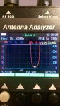
The UHF antennas all tested out similarly, <1.5 on their assorted target frequencies with a decent spread.

The VHF antennas, short whip, 19" whip, coaxial dipole, all check out similarly good.

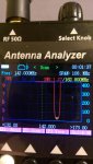
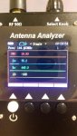
But the two dual band antennas, both Kenwood (came with the radio, no doubt it is genuine) and BF, both tested out at *19*, that's 1:19 SWR, on the target 144 MHz band.

WTF??

I know a dual band is a compromise antenna, but honest, if it was 19 I'd expect the radios to shut down. So, what am I seeing, really?
 

Rred

Member
Joined
Nov 21, 2014
Messages
830
It does graphs.
SURECOM RADIO Equipment
The SA-250.

It does not show a range of resonant frequencies per se, but it is capable of displaying SWR at a specific frequency. It claims to find an SWR of 1.26 at 159Mhz but that goes up rapidly to either side, hitting an SWR of 19 in the 140x ham area. Which in theory the dual-band antenna was made and matched for.

I don't think Kenwood would do THAT poor a job, I think I've have heard about that by now. Never did hear mention that a compromise dual-band ht antenna was THAT far out on 2m, and since I'm new to the meter and the Chinglish instructions...I'm presuming this is some kind of operator error at this point.

Maybe I'll hang a rat tail on it to see if putting in a proper counterpoise shakes the earth on this.
 

Rred

Member
Joined
Nov 21, 2014
Messages
830
OK, let's see if I can upload three pictures of the analyzer. They are 'attached" to this message, and I have uploaded them into a public album "SureCom Antenna Analyzer". The pictures should be self-explanatory. One is the SWR numbers at 144.

The other two are plots, the red line on the screen is the SWR plot.

One show the plot for the band, with the frequency of the lowest SWR of 1:1.27 at 162MHz.

The third has the little pyramid cursor at the bottom of the screen moved to bring 144.5 to the digital readings, and it shows 1:19 SWR for that frequency. The scale was left at SWR from 1-10 so the "19" is simply a flat red off the scale here, not actually part of the curve on the screen but that's not relevant.

PRCGUY? Any ideas?

This is not unique to one antenna, both a factory Kenwood and a factory BaoFeng show essentially the same numbers.
 

Attachments

  • swr at144.jpg
    swr at144.jpg
    65.6 KB · Views: 245
  • swr_curve.jpg
    swr_curve.jpg
    51.6 KB · Views: 239
  • swr_numbers.jpg
    swr_numbers.jpg
    47.3 KB · Views: 239

prcguy

Member
Joined
Jun 30, 2006
Messages
15,368
Location
So Cal - Richardson, TX - Tewksbury, MA
I would say your meter has a defect in reading the VSWR numbers. The scale in the first two pictures clearly shows you are on a 0 (1.00:1) to 10:1 scale and the cursor at the bottom of the resonant point is less than 2:1 and very close to 1.2:1, so 1.19:1 is about right.

On the bottom picture where its reading only numbers, 19.19 is a completely bogus answer IF the meter is measuring the exact same resonant point that shows 1.19:1 on the graphical scale. I would send the meter back and get another one or go for the AAI brand meter that works very well.
prcguy
 

Mikejo

Member
Joined
Jul 18, 2007
Messages
227
Location
Waltham,MA
I have the same SA-250 Antenna Analyzer.

I noticed that in the first Picture, the "White" pyramid icon is way back at 144.500 MHz, but where the swr dip (small yellow pyramid icon ) on the graph is up past the center frequency of 151.500 MHz

I'm pretty sure the 19.90 you are seeing coincides with the location of the white pyramid icon , not the small yellow pyramid icon at the bottom of the swr dip (valley shown in red on the graph).

I can't seem right now to be able to re-create the same situation on the "Quick 2" screen, perhaps I need to fiddle around with things a bit more.

If you could try to move the "White" pyramid icon to the same location as the "yellow"pyramid icon , it will read the proper VSWR.

If it can not be moved, perhaps it's a fault with the analyzer it self.

PRCGUY has the same analyzer, perhaps he can look to see if he can re-create this on his as well.

(Maybe mine is faulty) LOL!
 

Rred

Member
Joined
Nov 21, 2014
Messages
830
PRC-
But the TOP picture also shows 19.90 SWR at 144.500, in the numerical readings. The yellow triangle pointing down, in the red plotted notch line, marks the center of the notch. The white triangle, pointed up, marks on the graph to show where I have dialed the meter into 144.500.

So it isn't just the third picture and the numerical screen that shows 19.90, the plot does as well. And, even though I'm just on the 1:10 vertical scale here, which pushes "19.90" off the top of the scale, if I change the scale to allow plots up to 20, you betcha, the plot still shows 19.90 graphically when the frequency is 144.500. No freaky changes or jumps in the plot, a smooth notch that says these antennas shouldn't be playing well with the other kids.

??

Returning it certainly is an option, but the thing is, if I take a 19" VHF whip, or a plain 6" VHF helical, the meter DOES show them as properly working antennas at 144, with suitable single-digit SWRs.

It is just the dual-band antennas that show up queer on VHF. I'm not understanding how that is possible. (Two advantages of Amazon over Banggood, free Prime returns if it IS fubar, no waits on China Post.) Or do you have a USA source for the N1201SA UV ?
 
Last edited:

prcguy

Member
Joined
Jun 30, 2006
Messages
15,368
Location
So Cal - Richardson, TX - Tewksbury, MA
Your meter is reading different than my AAI meter even though many things appear to be similar between them. On my meter the downward pointing cursor you have centered in the apparent resonant portion of the antenna would read the frequency and the resulting VSWR at that frequency at the top of the chart, but your two pictures appear to be measuring something different.

Again, I would have to play with the Surecom meter to understand what its measuring. The first picture showing a truncated 19.9 something VSWR in red is a little disturbing.
prcguy


PRC-
But the TOP picture also shows 19.90 SWR at 144.500, in the numerical readings. The yellow triangle pointing down, in the red plotted notch line, marks the center of the notch. The white triangle, pointed up, marks on the graph to show where I have dialed the meter into 144.500.

So it isn't just the third picture and the numerical screen that shows 19.90, the plot does as well. And, even though I'm just on the 1:10 vertical scale here, which pushes "19.90" off the top of the scale, if I change the scale to allow plots up to 20, you betcha, the plot still shows 19.90 graphically when the frequency is 144.500. No freaky changes or jumps in the plot, a smooth notch that says these antennas shouldn't be playing well with the other kids.

??

Returning it certainly is an option, but the thing is, if I take a 19" VHF whip, or a plain 6" VHF helical, the meter DOES show them as properly working antennas at 144, with suitable single-digit SWRs.

It is just the dual-band antennas that show up queer on VHF. I'm not understanding how that is possible. (Two advantages of Amazon over Banggood, free Prime returns if it IS fubar, no waits on China Post.) Or do you have a USA source for the N1201SA UV ?
 

Mikejo

Member
Joined
Jul 18, 2007
Messages
227
Location
Waltham,MA
I was able to re-create your problem on my analyzer, what you have done is held down the "move cursor "button" and moved the cursor back to an area where the SWR is 19.90 (I was able to do this A few minutes ago).

pilot error?
 

WA0CBW

Member
Premium Subscriber
Joined
Dec 8, 2011
Messages
1,635
Location
Shawnee Kansas (Kansas City)
I believe your sweep is too wide. Try a smaller sweep. I think your meter is having difficulty resolving where the cursor is because the sweep is almost vertical.
BB
 

paulears

Member
Joined
Oct 14, 2015
Messages
790
Location
Lowestoft - UK
I may be stupid here - but you are measuring the VSWR at 144MHz, when the antenna is at it's design resonance at 160 odd - for business band. The 19 measurement is at a point on the curve well off the top of the screen. At 160ish, the VSWR is pretty good.

A quarter wave antenna with flat (as in horizontal) radials to the vertical element has a natural impedance of a bit over 70 Ohms, and this is why many ground plane elements are tilted down, it lowers the impedance to the usual 50 Ohms or there about. This is perfectly normal behaviour. It also is the reason why sometimes even when you measure correctly, you need to trim the length to make the match. The actual mount itself also spoils the impedance - so a small connector like an SMA will have a shorter whip than one in a PL259, because of the length of the connector messing the measurements up too!

We have a high VSWR out of the antenna's natural bandwidth, and a good one, higher up in frequency. Why are we thinking something has gone wrong? This seems perfectly normal. The meter is simply reading VSWR/Frequency in the display. 1st pic, bad at 144, then good at 162 in picture 2. In picture 3, there is presumably capacitive reactance, based on the - figure, inductive reactance normally shows a + symbol.
 

prcguy

Member
Joined
Jun 30, 2006
Messages
15,368
Location
So Cal - Richardson, TX - Tewksbury, MA
A quarter wave monopole with infinite flat ground plane under it has a natural impedance of 36 ohms. Make it a quarter wave ground plane with three or four radials at a right angle or flat and its higher than 36 ohms but lower than 50 ohms. Bending the radials downward will raise the impedance.

A 1/2 wave dipole in free space is about 72 ohms and higher impedance than a 1/4 wave ground plane partially due to the reduced capacitance between the elements compared to a ground plane.

A VHF or UHF quarter wave whip on an antenna analyzer will be higher than 50 ohms due to the lack of capacitance between the whip and insufficient ground plane of the analyzer metal box.
prcguy

I may be stupid here - but you are measuring the VSWR at 144MHz, when the antenna is at it's design resonance at 160 odd - for business band. The 19 measurement is at a point on the curve well off the top of the screen. At 160ish, the VSWR is pretty good.

A quarter wave antenna with flat (as in horizontal) radials to the vertical element has a natural impedance of a bit over 70 Ohms, and this is why many ground plane elements are tilted down, it lowers the impedance to the usual 50 Ohms or there about. This is perfectly normal behaviour. It also is the reason why sometimes even when you measure correctly, you need to trim the length to make the match. The actual mount itself also spoils the impedance - so a small connector like an SMA will have a shorter whip than one in a PL259, because of the length of the connector messing the measurements up too!

We have a high VSWR out of the antenna's natural bandwidth, and a good one, higher up in frequency. Why are we thinking something has gone wrong? This seems perfectly normal. The meter is simply reading VSWR/Frequency in the display. 1st pic, bad at 144, then good at 162 in picture 2. In picture 3, there is presumably capacitive reactance, based on the - figure, inductive reactance normally shows a + symbol.
 

Rred

Member
Joined
Nov 21, 2014
Messages
830
A reply relayed back from Surecom direct (they're not going to join a forum just to post a reply) :
-----
As we haven't registered on that fourm, therefore would you please helping us to post the reply

Let me explain the what happen of situation of that post

In 1st photo, it can't show the best frequency of the antenna, as the user using click the [MOVE CUR] to move the index of the correct result [see pic]

therefore, the display SWR:19.9/144.500mhz <=== it show the SWR in frequency 144.500mhz, as user mover the index to 144.500mhz

In 2nd photo is correct show the best frequency of the antenna is 162.800mhz which SWR is 1.27

In 3rd photo, the result is correct , according to the 1st photo already show that in frequency 144.500mhz, SWR is 19.9, if you change the frequency 162.800mhz in 3rd photo, then the SWR will show 1.27
-----

If I'm reading them correctly, they're saying the readings are correct, the cursor is in the right place, the antenna just has a huge SWR at 144.5 and as Paul mentions, apparently is best used for 160MHz business band not ham band VHF.

?!

Leaving the two questions of:
1-Why doesn't that SWR burn up the radio?
2-Does anyone actually make a dual-band antenna that is tuned for 144/440 NOT 160/440?

Or do I not understand what SureCom said?
 

Mikejo

Member
Joined
Jul 18, 2007
Messages
227
Location
Waltham,MA
Well, Apparently Surcom agrees with what I had mentioned in post #6 above.

The user had moved the white cursor backwards to 144.500MHz and shows what the vswr for that antenna would be at 144.500MHz. If the user were to move the white cursor back to where the yellow cursor is, it would show the best vswr for this antenna at 162.800MHz (best vswr for the VHF portion of the electro magnetic spectrum).

What the analyzer truly shows is this particular antenna is "Doo Doo" at 144.500MHz.

Like was also mentioned above is the question as to why the Radio like's it, and does not burn up?
 

prcguy

Member
Joined
Jun 30, 2006
Messages
15,368
Location
So Cal - Richardson, TX - Tewksbury, MA
Radios don't just burn up and can usually handle very high SWR for a brief time. In fact, I've tried to damage various radios on purpose by putting a rubber band around the mic PTT and walking away for an hour with no antenna connected. I've done this to many CBs and a good number of VHF/UHF radios and have never damaged one yet.
prcguy

A reply relayed back from Surecom direct (they're not going to join a forum just to post a reply) :
-----
As we haven't registered on that fourm, therefore would you please helping us to post the reply

Let me explain the what happen of situation of that post

In 1st photo, it can't show the best frequency of the antenna, as the user using click the [MOVE CUR] to move the index of the correct result [see pic]

therefore, the display SWR:19.9/144.500mhz <=== it show the SWR in frequency 144.500mhz, as user mover the index to 144.500mhz

In 2nd photo is correct show the best frequency of the antenna is 162.800mhz which SWR is 1.27

In 3rd photo, the result is correct , according to the 1st photo already show that in frequency 144.500mhz, SWR is 19.9, if you change the frequency 162.800mhz in 3rd photo, then the SWR will show 1.27
-----

If I'm reading them correctly, they're saying the readings are correct, the cursor is in the right place, the antenna just has a huge SWR at 144.5 and as Paul mentions, apparently is best used for 160MHz business band not ham band VHF.

?!

Leaving the two questions of:
1-Why doesn't that SWR burn up the radio?
2-Does anyone actually make a dual-band antenna that is tuned for 144/440 NOT 160/440?

Or do I not understand what SureCom said?
 

Mikejo

Member
Joined
Jul 18, 2007
Messages
227
Location
Waltham,MA
Just being a bit hyperbolic!

I was meaning with such a bad vswr "19.90" that could damage a radio's finals. years ago, I blew the finals on a mobile CB tby ransmitting without an antenna, and had heard of many instances of ruined radio's from other cases of transmitting with a damaged coax e.t.c.
 

Mikejo

Member
Joined
Jul 18, 2007
Messages
227
Location
Waltham,MA
I would just going to ask a question of those more experience than I.

I would like to make a 50 ohm dummy load for my SA-250 Antenna analyzer.

The analyzer comes an SMA female onto which I've placed an SMA to BNC female.

I'm thinking of using a BNC Male to RCA Male with a 1/4 watt 51 ohm carbon film Resistor soldered across the center and shield

(I suppose I could get some kind of SMA connecter, and soldier the same Resistor across the center and shield instead).

Does this sound like an ok idea?
 

prcguy

Member
Joined
Jun 30, 2006
Messages
15,368
Location
So Cal - Richardson, TX - Tewksbury, MA
What you are proposing will work to a certain frequency, but you might want to test your home made load with some known test equipment to see how good it is. You may find its good to just a few MHz or it might make it past 30MHz, but I doubt if it will be very good in or above the VHF range. I would be looking at a return loss of at least 30dB and hopefully closer to 40dB to be considered good.

In many cases you can get a very good SMA 50 ohm load on Ebay for just a few $$ and some are rated to 18GHz or higher.
prcguy


I would just going to ask a question of those more experience than I.

I would like to make a 50 ohm dummy load for my SA-250 Antenna analyzer.

The analyzer comes an SMA female onto which I've placed an SMA to BNC female.

I'm thinking of using a BNC Male to RCA Male with a 1/4 watt 51 ohm carbon film Resistor soldered across the center and shield

(I suppose I could get some kind of SMA connecter, and soldier the same Resistor across the center and shield instead).

Does this sound like an ok idea?
 
Status
Not open for further replies.
Top