3 Element Beam Questions

Status
Not open for further replies.

SpugEddy

Member
Premium Subscriber
Joined
Oct 4, 2015
Messages
438
Location
Camden County South Jersey
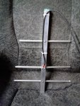
Below is, yet another, DIY antenna. It's a 3 element
beam.
This antenna is still in the design phase and this is
my prototype. When I finished, I put it to a short test
with SWR meter. Then I did a short test with a CCR
handheld. I got a pretty good SWR and I was able to,
once again, open repeaters that I cannot open with the
rubber ducky, nor a Nagoya 19" telescoping antenna. I
get some good " S meter reports" from friends. My SWR
on both my Motorola and the CCR is 1.5:1 average.
(I have a friend bringing over an antenna analyzer when
he can)

I'm looking for input for a possible matching stub plus the following:
1) Do I need one?
a) Would you be happy with a 1.4:1 on your Motorola?
2) Do I have to put the stub on both the center conductor and the shield or just the center?
3) Even though it's all I have, is 20' off the ground enough?
4) Most important. How do I figure out what the gain is of this antenna?
 

jwt873

Member
Premium Subscriber
Joined
Dec 1, 2015
Messages
1,625
Location
Woodlands, Manitoba
An SWR of 1.4 to 1 is perfectly OK

If this is your SWR, there's no need to match anything. A 1:1 balun might help to eliminate common mode currents on the coax.

For a Yagi to radiate as designed, it needs to be at least one wavelength off the ground, so 20 feet up is OK.

You can determine the gain mathematically. This site has an online calculator: https://www.changpuak.ch/electronics/yagi_uda_antenna_DL6WU.php

I'm interested in how you're feeding the driven element. Like KC4RAF points out... It appears that both the center conductor and the outer braid are almost touching. How do they connect to the elements?
 

prcguy

Member
Joined
Jun 30, 2006
Messages
15,359
Location
So Cal - Richardson, TX - Tewksbury, MA
It almost looks like the handle end where the coax exits has a shorter element and that end should be the reflector with a longer element. What band is this for and where did the element lengths come from?
 

SpugEddy

Member
Premium Subscriber
Joined
Oct 4, 2015
Messages
438
Location
Camden County South Jersey
Are those 2 ring terminals screwed to the boom? No insulators for the elements? It looks like a short all the way around.

No. Shoulder washers, rubber washers, then 2 stainless washers for the
fork connector. The screws are totally isolated from the boom. Thought I
had a good pic of the connections but I don't. My first test was done with
my fluke meter and no shorts (or continuity) where there shouldn't be.
 
Last edited:

SpugEddy

Member
Premium Subscriber
Joined
Oct 4, 2015
Messages
438
Location
Camden County South Jersey
It almost looks like the handle end where the coax exits has a shorter element and that end should be the reflector with a longer element. What band is this for and where did the element lengths come from?

Again... This is the reason I run these projects past you
guys here at RR. Apparently, I goofed. You are correct
PRCGUY. The reflector and director need to be swapped.
I wonder what kind of results I'll get when I swap them.
More to come on that one. THANK YOU

2nd, calculations were made for 462 - 467 Mhz. I believe
I made my calculations for 465 Mhz because I do use the
simplex channels.
 

SpugEddy

Member
Premium Subscriber
Joined
Oct 4, 2015
Messages
438
Location
Camden County South Jersey
I did have another question.
Since the boom and the elements are isolated, how important
is the overall length of the boom?. The plans and calculations
call for a 16" boom and mine is not trimmed to 16". Right now
it is 18" with the excess at the tip or the front of the antenna.
The "corrected" director end
 

KC4RAF

Member
Joined
Sep 30, 2006
Messages
1,579
Location
Davenport,Fl.- home to me and the gators and the s
SpugEddy, you're off to a great start sir. Experimenting is a joy of life.
To help you along with antenna building, a member here at RR, K7MEM, has a website for building antennas, (as well as other useful electronic information).

Martin E. Meserve - K7MEM

He has thrown in some basic electronic theory as well to help the budding experimenter along. I've used his site several times and really appreciate his work sharing his knowledge.

edit: if the boom is metal, the length can be of importance. Check the site I've included and on the right side, click on "Antennas - VHF/UHF". You'll see a selection of different designs.
 
Last edited:

SpugEddy

Member
Premium Subscriber
Joined
Oct 4, 2015
Messages
438
Location
Camden County South Jersey
SpugEddy, you're off to a great start sir. Experimenting is a joy of life.
To help you along with antenna building, a member here at RR, K7MEM, has a website for building antennas, (as well as other useful electronic information).

Martin E. Meserve - K7MEM

He has thrown in some basic electronic theory as well to help the budding experimenter along. I've used his site several times and really appreciate his work sharing his knowledge.

edit: if the boom is metal, the length can be of importance. Check the site I've included and on the right side, click on "Antennas - VHF/UHF". You'll see a selection of different designs.


Thank you Sir. Looks like a great site. Don't know how
I've been missing it all this time
 

majoco

Stirrer
Joined
Dec 25, 2008
Messages
4,283
Location
New Zealand
No Balun? Dipoles are balanced and you have taken care to isolate both elements from the boom but then fed them with an unbalanced coax feed.
 

SpugEddy

Member
Premium Subscriber
Joined
Oct 4, 2015
Messages
438
Location
Camden County South Jersey
No Balun? Dipoles are balanced and you have taken care to isolate both elements from the boom but then fed them with an unbalanced coax feed.

Balun was another question I had, but I was taking
baby steps. (I was trying not to be the little kid
tugging on the pants of Dad asking 20 questions)

I did see one person's DIY for a 3 element and he took
the coax feed line and wrapped it around the boom about
5 - 7 times very close to the feed point. I was trying to look
into that but cant find that page in my browser
1:1 is what I need, correct?
 

prcguy

Member
Joined
Jun 30, 2006
Messages
15,359
Location
So Cal - Richardson, TX - Tewksbury, MA
The boom length should not matter, you can add some for a handle like you did or make it 6ft long, not critical. The important things are the length of the elements being correct for the element diameter and for being insulated from the boom vs attached to a metal boom, and the spacing between the elements. In the case of the elements gong through a metal boom the boom diameter becomes part of the equation.

For the driven element, as others have mentioned its a balanced dipole and will usually be less than 50 ohm impedance due to the close proximity of the other elements. For an insulated boom with two separate halves of a dipole (in your case) I like to use a haripin match, which is simply a loop of wire that shorts across the coax attachment. The size and length of the hairpin is not super critical but I would estimate a loop of wire about 2" long with similar spacing to your feedpoint screws would be a good start. I would make a loop about 3" long and check the match, then shorten 1/2" and check again until the match bottoms out at perfect.

You should also have a good 1:1 choke balun and one turn (loop) of small coax around a 43 mix ferrite snap on bead would be a good start. Or at least two to three 43 mix beads in series clamped around the coax.

I did have another question.
Since the boom and the elements are isolated, how important
is the overall length of the boom?. The plans and calculations
call for a 16" boom and mine is not trimmed to 16". Right now
it is 18" with the excess at the tip or the front of the antenna.
The "corrected" director end
 

SpugEddy

Member
Premium Subscriber
Joined
Oct 4, 2015
Messages
438
Location
Camden County South Jersey
I actually tried it PRCGUY and, it must be me, but I just couldn't
get it set right and I did understand your hairpin was a U shape.
Then I remembered the coaxial loop. I found the
obnoxious formula for determining the length of the coax (a.), in one
of my old memo books, and I gave it a shot. I started with 9-7/8"
and after a few tests, I ended up with a 9¼" piece with a very
low SWR. I still need to check it out with an antenna analyzer to
find the resonant frequency, but it looks like I may have stumbled
on the right recipe for this build.

Ferrites are ordered and expected here on Tuesday

(a.) =
{(3 x 10^8 ÷ ƒ x 10^6)} x Velocity factor = Length in meters ÷ 39.37 =
Length in Inches

Last night's test was a CCR with 2 watts. Opening a repeater
20+ miles away with absolute "ZERO" static or interference.
That was with the antenna 7½ feet off the ground.

Also, thank you again for pointing out my goof with the swapped
elements. I could have banged my head for days until I noticed
the error.

Thank you all for the replies and your input. Pics at the end when
I am finished.
 

prcguy

Member
Joined
Jun 30, 2006
Messages
15,359
Location
So Cal - Richardson, TX - Tewksbury, MA
There is a 4:1 balun that uses a 1/2 wavelength loop of coax but that's not what you want for the driven element on your antenna. You have an ungrounded center fed dipole that will be less than 50 ohms and the coax loop balun is for feeding a 200 ohm antenna.

The hairpin loop is simply a length of wire or other metal formed into a U that shorts out the driven element with some inductance. It will help match 50 ohm coax to a lower impedance which is what you need.

I actually tried it PRCGUY and, it must be me, but I just couldn't
get it set right and I did understand your hairpin was a U shape.
Then I remembered the coaxial loop. I found the
obnoxious formula for determining the length of the coax (a.), in one
of my old memo books, and I gave it a shot. I started with 9-7/8"
and after a few tests, I ended up with a 9¼" piece with a very
low SWR. I still need to check it out with an antenna analyzer to
find the resonant frequency, but it looks like I may have stumbled
on the right recipe for this build.

Ferrites are ordered and expected here on Tuesday

(a.) =
{(3 x 10^8 ÷ ƒ x 10^6)} x Velocity factor = Length in meters ÷ 39.37 =
Length in Inches

Last night's test was a CCR with 2 watts. Opening a repeater
20+ miles away with absolute "ZERO" static or interference.
That was with the antenna 7½ feet off the ground.

Also, thank you again for pointing out my goof with the swapped
elements. I could have banged my head for days until I noticed
the error.

Thank you all for the replies and your input. Pics at the end when
I am finished.
 
Status
Not open for further replies.
Top