160-20m LOG loop-on-ground

Status
Not open for further replies.

nanZor

Active Member
Joined
May 28, 2009
Messages
2,807
G4JNW got me thinking about a "hybrid" log.

While this project is about being totally on ground, how about a hybrid, where part of it is on ground on part is elevated somewhat? That would be interesting to model to make sure it's not a waste of time.

Two options for the 50x25 area just to keep it stealthy and safe:

1) For the "open loop" version, with the feedpoint in a corner of your yard, run the main "U" wire up and along a property fence. The other side of the transformer just has the 25 foot "radial" running / hidden across the ground near your patio.

2) For the true closed loop, do the same - most of the loop is run up and along our property fence, but when it approaches your back step patio, just drop it down to the ground and at one side of the patio is the transformer / feedpoint.

That would really make for an interesting modeling job - I'd just put it up and test it - knowing that perhaps that hybrid technique results in an upward pencil-pointy lobe. I just don't know... :)
 

g4jnw

Member
Joined
Oct 29, 2018
Messages
12
Location
lynemouth, northumberland
Just as an aside - Would you believe that there is a LOGG (Loop on the ground group) on Facebook??

https://www.facebook.com/groups/319198328872015/

Onward...Mike

A friend of mine started it, its got quite a few members now.

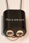
One thing i have found out and just posted on the facebook group is that ive been making a mistake when winding the binocular ferrites, I read into the instructions wrongly and thought that a full turn was right round, in effect 1 and a half turns as it comes back out of the same side.

So ive been winding 2 and a half turns (which is actually 3) and 6 and a half turns which is actually 7

Although i have decent results i wonder if i do it correctly if the results will be better.

Here is how i found out i was doing it wrong!!

https://m1kta-qrp.blogspot.com/2018...eFpzeopXWjouy9VCwNtKayaLVlN8rdjRIowZjeQCi2kGw

Plus this image:
 

Attachments

  • One_turn.jpg
    One_turn.jpg
    31.9 KB · Views: 114

nanZor

Active Member
Joined
May 28, 2009
Messages
2,807
Wow - maybe I'll have a reason to join Facebook now ...

Thanks for the reminder on how to wind the cores. I did exactly the same wrong thing for a similar project a few years ago.

The binocular core of the PAR / LNR precision EF-SWL antenna does really well it seems down to about 1 mhz. Just sayin' for those that want to throw down an off-the-shelf solution - and removing the jumper for isolation. Sure enough though winding your own is a total kick.

160 meters with the 60-foot loop: my best dx so far from LA was to KH7B in Hawaii, but at 160 I think I can safely say that a tuner really helped tune out some of the major system reactance and made KH7B armchair copy for the last cw contest. He station did 99% of the work, but still ... 160 on a small loop benefitted from a tuner.
 

g4jnw

Member
Joined
Oct 29, 2018
Messages
12
Location
lynemouth, northumberland
Been so much rain here for weeks it seem, North of England famous for lots of things, particularly rain.

Update, since the ALA-100 was doing fine and i had wound the binocular ferrites wrong, the ALA-100 is back in place, great for FT8 but lifts the noise up more than i want.

When the rain stops im going to put the binocular ferrites back in but in the meantime i read back on the threads, i have 2 things in my junk box. A very old MFJ huge line isolator, made before the 915 and a noolec 9-1 balun i bought to use with my SDRplay in a reverse mode to the HiZ port which i found useless for that job.

Thinking of what changes i could make before i rewind the binocular ferrite.

I could replace the ALA-100 with the noolec 9-1 balun and also put in place the old mfj line isolator.
I notice in the thread ages ago you used the noolec but cut the track on the reverse of the board. Is that where the only track is, shown up on the image enclosed? Also placement of the line isolator i would imagine is outside and right after the noolec? The line isolator looks to be very waterproof so no problems with that laying on the ground. The noolec will have to go in a waterproof container.

What do you think?
 

Attachments

  • IMG_2153.jpg
    IMG_2153.jpg
    27.4 KB · Views: 88

nanZor

Active Member
Joined
May 28, 2009
Messages
2,807
Yep - see that single trace? Scratch through it for physical *galvanic* isolation from the braid.

And if you look closer, you'll see two through-hole pads (might be on front side), where one could attach wires to make it a switchable isolated / shared ground option with a switch. Or I just suppose solder-blob it back together. I recommend scratching through (and ohming it out with a multimeter to be sure), rather than a knife - which has a tendency to slip and cut right through the fingers holding the balun. I came close to injury, so I just used a fine screwdriver to scratch through.

The push-in wire connectors are kind of bogus for anything but temporary setups. If you do use it, I'd just solder a decent connector for the loop wires to the bottom of the board where the push-in connectors are.

Re the ferrite common-mode isolator: Instead of a stressed out adapter right after the nooelec 9:1, I used a small 1 foot sma - to - so-239 jumper to the CMC. In fact, using the 1 foot jumper allowed me to use other ferrites with the jumper looped through them.

Some may question the effectiveness of the CMC following a galvanic isolator. I prefer to use it just to cover my butt, since forum threads about the subject can get, um, a bit testy at times elsewhere. :) I'd especially recommend it when using the asymetrical "open loop" version. At the very least, it doesn't hurt.
 

g4jnw

Member
Joined
Oct 29, 2018
Messages
12
Location
lynemouth, northumberland
will give the nooelec a try then, i have a good collection of clip on ferrites that would go over the RG58 coax thats another alternative rather than use the MFJ line isolator, i know the MFJ one has 50 ferrites in, tried once to open it but its really solid, pleased now i didnt cut it open. If i do use clip on ones not sure how many to use, think i have around 25 in the junk box.
 

prcguy

Member
Joined
Jun 30, 2006
Messages
15,339
Location
So Cal - Richardson, TX - Tewksbury, MA
I'll be heading to the CA high desert tomorrow testing antennas and other things. One antenna I'm bringing is a high power Eyring ELPA-501 which lays on the ground and should be very quiet on receive like the Log. I'll compare it to a 130ft 80-10m end fed and I'm especially curious how the Eyring will do on 160m transmitting.
 

nanZor

Active Member
Joined
May 28, 2009
Messages
2,807
350 foot log? Cool - although I'll have to model that pronto to see what kind of weird squirt that puts out on 20 meters. :) I'll check that out...

prcguy - neat to see how the ELPA does in the field. It's all about s/n and directivity in wanted directions.

Notes from my testing on the log - with 15 foot sides, the "resonant" point being on the ground like this is nearer 12 mhz as seen on my analyzer and also in EZnec. Of course that will change depending on ground quality.

Not that it matters, but because I'm compelled to make the loop sides smaller to 14 feet, so that it is resonant on the ground at 14mhz, I'm going to cut it since I don't think the loss of 4 feet overall is going to make a difference. But, 14 feet sides resonating at 14mhz makes a handy mnemonic. I'll do it for fun and let anyone know if the golden dx suddenly shows up. :)
 

nanZor

Active Member
Joined
May 28, 2009
Messages
2,807
Can you make a LOG too large?

Yes, and when you do, you end up with an uncontrolled random pattern of lobes going all over the place.

I think it's very cool what Chris has done with his 350 foot LOG, but anything higher than about 2 mhz on that project starts to go into the uncontrolled patterns - nvis at certain angles, skewed to one side or the other, etc etc. In other words, reception could be FAR worse than using a smaller log in the first place.

I'm just saying - that HUGE log project is a lot of fun, but don't judge performance overall when the loop far exceeds 1 wavelength in circumference at the highest band of interest. Unless you model it, and like that kind of response, you may be disappointed in some directions.

Something that large is pretty cool for 160 meters and lower, but higher than 2mhz - party time with random angles. :)

But Chris's cool project got me thinking : I'm going to have to do more research on how VF may be affecting things - that is, with a typical 0.9VF of insulated wire, how much is that affecting *my* log's pattern up at 20 meters? I do know that you aren't penalized in pattern response by using a smaller loop. But 350 feet AND the VF to contend with? I'll do some research / modeling / listening and see what happens when I shorten my loop to 14 feet per side.
 
Last edited by a moderator:

nanZor

Active Member
Joined
May 28, 2009
Messages
2,807
Chris's 350 log and SDR pretty awesome!

It's so nice, it's worth mentioning twice - an awesome demo of the log antenna:

http://sdr.hfunderpants.com:8073/

Just didn't want to come across as critical of someone who took the time to lay one of these down, and put up a nice SDR for us all to share.

Sent a message to maybe incorporate a smaller log in the future for the higher freqs. But in the meantime, it's waaay cool! Nice work Chris.
 

nanZor

Active Member
Joined
May 28, 2009
Messages
2,807
Velocity factor not significant

My main concern about the VF is not so much about resonance, but what it might do to the pattern.

I didn't see any significant change in either when I put 6 inches of insulation around #18 wire only 1/8th inch above ground in EZnec. I'm sure a more skilled modeler than I could find some interaction, but I think the 800 pound gorilla of ground loss hides it. :)

BUT, EZnec didn't complain about the *insulation* being underground either!

I'm not going to go to the whole underground thing, but it did get me thinking that maybe for some people, instead of tacking the wire to the ground, putting it out in plain sight in some form of tubing might be ok.

Ie, you have a gardner or other safety issue that you don't want anyone getting tangled up in - even flat on the ground. Maybe put it inside irrigation pipe/tubing or something in plain sight so it won't get dismantled.

Or perhaps a safety issue for field-day, where the tubing can easily be seen or stepped on without worry. Or maybe your loop needs to cross a dirt driveway or other access - put it inside a tube, bury it very shallow, and get on with it.
 

krokus

Member
Premium Subscriber
Joined
Jun 9, 2006
Messages
5,992
Location
Southeastern Michigan
It's so nice, it's worth mentioning twice - an awesome demo of the log antenna:

http://sdr.hfunderpants.com:8073/

Just didn't want to come across as critical of someone who took the time to lay one of these down, and put up a nice SDR for us all to share.

Sent a message to maybe incorporate a smaller log in the future for the higher freqs. But in the meantime, it's waaay cool! Nice work Chris.
That is a nice page. I will have to explore that more, on a PC.

Sent using Tapatalk
 

nanZor

Active Member
Joined
May 28, 2009
Messages
2,807
Smaller loop? 54 feet vs 60 feet comparison:

Being paranoid about a skewed pattern at the high end of the band coverage, and because modeling does not always reflect the real world, I decided to cut my loop shorter so that I wouldn't skew 20 meters.

Basically that simply means that I now have 14 foot sides of the square, vs 15 feet.

Heh, PLENTY of signal strength - the directly attached Kenwood 590s and Alinco R8T didn't notice any change. It will take a lot of listening to see if I can detect any "skew" in the pattern up on 20 meters, and I kind of doubt I'll really be able to tell up there. But we'll see.

However, when attached to the Target HF3 which I usually run with an MFJ tuner/preamp just for a little extra oomph on that radio, I noticed the following which would most likely be of interest to amateurs and not swl'ers:

The cap and inductor settings for both 20 meters and 40 meters is the same. Both 80m and 160m need LESS inductor for peaking by ear. Interesting - I would have thought I'd need more, not less.

Just an observation, and totally unscientific. Sure I have a 2:1 swr on 20 meters, but that means nothing for an rx-only antenna which is basically designed to be non-resonant anyway.

I'll see what my ear turns up over the next few days (grin), but really overall the only thing that *may* have been improved is the pattern on 20m, since going smaller, rather than exceeding a wavelength keeps the pattern tight.
 

prcguy

Member
Joined
Jun 30, 2006
Messages
15,339
Location
So Cal - Richardson, TX - Tewksbury, MA
Back from my desert trip and got to use the Eyring lay on the ground antenna on several HF bands. In its stock configuration it was generally about 10-12dB down from a 130ft long resonant 80-10m end fed on 40 and 80m up at 25ft. On a few contacts the Eyring was about 3dB down from the end fed and those stations were off the ends of the Eyring. Basically it performed about like I expected and the match over the 80 through 10m band was less than 3:1 and usually better than 1.5:1 within the ham bands.

Then we tried 160m and got a big surprise, it worked better than any antenna I've ever used on 160m. Running about 500w I had about as good a signal as anyone else using a big antenna and near full legal limit as reported by a friend monitoring on a remote SDR receiver. Everyone we talked with was surprised the antenna was on the ground and commented on my big signal.

I initially tried it in stock 300ft dipole mode on 160m, which did not have a great match and then tried V shaped elements as recommended in the manual. I didn't have an extra set of 150ft elements but did have two wire spools 234ft long each which made a pair of 117ft V shaped elements and that matched and worked a little better on 160m. Then I tried the full 234ft elements making a 468ft dipole on the ground and that worked a little better still on 160m but I could tell 80 and 40m reception was down slightly from the stock 300ft dipole mode. Seems like Eyring figured out the best lengths for its stated 2 through 65MHz range and changing that will degrade one end of the range or the other.

I have not tried the smaller 15ft per side type of LoG yet but from descriptions of its use I would say the stock Eyring will give a much higher signal level on receive at the cost of needing a lot more real estate. Plus you can transmit on the Eyring and put out a signal that is better than a mobile antenna and it doesn't need any trees or mast and its almost invisible as evidenced by me tripping over the wires all weekend.
 
Last edited:

ka3jjz

Wiki Admin Emeritus
Joined
Jul 22, 2002
Messages
25,388
Location
Bowie, Md.
To get this back to listening (ahem!) I heard that R Verdad Guatemala 4055 was coming in very loud this evening, so I tried Chris' SDR and 350 foot LoG. There it was, clear as a bell. Perhaps a power or antenna change (or maybe both) helped, as this one is usually difficult to hear. LSB clears up the STANAG sounding interference nicely. And 252 khz Algeria was pretty easy copy too - see the reports in the other forum.
 

ka3jjz

Wiki Admin Emeritus
Joined
Jul 22, 2002
Messages
25,388
Location
Bowie, Md.
A couple of suggestions here - don't shy away from defining terms like 'Eyring'. And if you are testing on the ham bands, be sure to give the frequency range, unless you are hearing a station as I was. I know that is a fairly technical topic but we might have any number of newcomers trying to read this, and it's way too easy to slip into the jargon. We're not all hams here, after all...Onward, please.
 

nanZor

Active Member
Joined
May 28, 2009
Messages
2,807
Wow - great stuff. But just a warning to readers of this thread - sometimes LESS is more. Ie, you may not need 350 foot loop to accomplish the same - in fact, depending on frequency, one may end up with a high-gain grab-bag of skewed reception angles that may or may not work.

Chris has done a great job. If you visit that awesome SDR site, you'll see something similar to the 60-foot log - wall to wall AM BCB stations at night. That's because whether it is 60 foot in circumference, or 350 feet, at those frequencies it is basically a huge vertical omni electrically. (on-ground means minimal to no horizontal reception) Thus, BCB dx'ing may consist of knowing the right sign-on / sign-off times, rather than hoping for any major directionality. Just a warning that your little loopstick inside a radio might do a better job if directionality is part of your toolkit.

Without denigrating anyone's project, I'd really recommend using EZnec first to get an idea of where you are headed depending on size, shape, or length. It will cut down on a lot of trial-and-error, although I admit that's half the fun.

Here's an easy way to get into the directionality / matching prediction game with just the dipole on ground:

1) Grab a copy of the EZnec demo.
2) Open the "BYdipole.ez" file.
3) Change the "wires" to bring the Z down from 30 feet to 0.1 (zero-point-one) feet on each end. You may also want to change the allowable segments to 20 - the max for the demo.
4) If not done already, change the "Ground Type" to Real / Mininec
4) Run the "FF PLOT" on it. Change your plot type to "3D" if you want to rotate the wireframe around.
5) Change the frequency and run the FF Plot again.
6) Change the overall length of the dipole in the WIRES area, and run your FF Plots.

This obviously is just a quickie recipe, and not even a real EZnec startup guide. But it might show the interested user how important the directionality of an antenna that can be -50db down in strength is. :)

Once you tackle the simple on ground dipole, making an on ground loop, and looking at it's properties will be easier.
 

nanZor

Active Member
Joined
May 28, 2009
Messages
2,807
What I'm really trying to say:

Like an amateur using a 43-foot vertical on 6 meters, or a scanner listener trying to listen to 800mhz comms on an 8 foot long CB whip, you may have non-optimal reception due to scattered pattern lobes from an antenna that is too large compared to frequency. In some cases, it may work, and others not depending on conditions or user expectations.

Electrically, the LOG is a vertical antenna, since the horizontal is attenuated massively by the ground loss. But to make it more fun, since this "vertical" is fed on one side of a loop, in addition to weird lobes when made too long, they can also move from side to side as well. That's cool if that's what you want. I prefer the more controlled omni of a loop that is less than an electrical wavelength, typically no more than 934 / f mhz long in feet circumference at the highest frequency of interest.

EZnec will get you in the ballpark for what to expect if you exceed a wavelength, although the actual ground conductivity at your site will change things from the modeling.
 
Status
Not open for further replies.
Top