Antenna lengths per band

Status
Not open for further replies.

SlipNutz15

Wacker
Feed Provider
Joined
Aug 6, 2005
Messages
633
Location
Central PA
So am I supposed to just leave the antenna where it is and then use a splitter and run to a second scanner instead and hope for the best?

My parents have a scanner in the kitchen and I would like to have it hooked up to the antenna as well. Would having a splitter on it do anything to the signal strength that I would be able to notice?
 

SlipNutz15

Wacker
Feed Provider
Joined
Aug 6, 2005
Messages
633
Location
Central PA
Here's the updated picture(s) of the UHF antenna. Pics up 460 band very well and the 46.060 band awesomely as well... kind of amazing.
 

Attachments

  • P8120003.JPG
    P8120003.JPG
    22.4 KB · Views: 428
  • P8120004.JPG
    P8120004.JPG
    24.8 KB · Views: 660

kf4lne

Member
Joined
Jul 31, 2005
Messages
430
Location
Bristol, VA
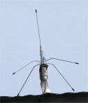
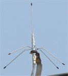
Slip - Very nice antenna, but are the ground radials attached to th shield of the coax or to the center conductor? That looks like a 3/8x24 thread CB style antenna mount with the radials attached to the little spacer that goes between the mount and the antenna threads..is that how that is built?


AI42 - I'm not argueing with you, I'm just pointing out that since he most likely isn't a communications specialist and probably doesent have all the gear needed to design and impliment a perfect antenna system that a comprimise antenna system will work in his case. While using a single antenna resonate at the bands he wants to receive would be better than using 2 seprate antennas, 2 seprate antennas will work for what he needs to do. I am also pointing out that building an antenna system for 2 specific bands will usually perform better than trying to use a commercially produced scanner antenna. The important thing here is that he wants to receive low band FM and UHF FM and i seriously doubt he is trying to hear weak signal UHF CW EME from the other side of the planet, and in all practicality with a scanner being able to gain that extra percent of signal is probably not going to make much of a difference, but in the rare case it will. As for spacing the antennas that far apart I would fully expect multipathing, and if he lives in an area where there are tall buildings and mountains and other large objects for the signal to reflect off of i would also expect multipathing. Remember, this is only a scanner antenna we are talking about, not an uber-god antenna to hear the Mars rovers. he wanted to build an antenna, so we have provided the information for him to build an antenna and provided him the information needed to do such. You know as well as I that when telling someone how to design and build an antenna system who has never done it before, you start with the basics and leave the insanely technical aspects for another time, otherwise people get confused because there are a lot of gaps as to teh whys and hows that are missing in between. I'm not going to nit pick details over a simple scanner antenna project, I know that using multiple antennas on one receiver for several different bands will have problems, but in general the listener will never notice the effects because the problems created are so insignificant when doing recreational radio monitoring that you cant tell. Now if he was all about doing insanely technical monitoring with a $10k service monitor, then we could work out the details for a optimized single antenna or antenna system. Anyway, back to the thread at hand and we can save the super-technical stuff for when someone wants to hear 1296MHz CW EME :)
 
Last edited:

SlipNutz15

Wacker
Feed Provider
Joined
Aug 6, 2005
Messages
633
Location
Central PA
So if I make my low-band antenna and keep it like right next to the antenna I have for the UHF antenna, things should work for picking up low-band a little better? If not, I won't even attempt it.
 

kf4lne

Member
Joined
Jul 31, 2005
Messages
430
Location
Bristol, VA
Slip - you are using a scanner. Try the low band antenna by its self and then try both antennas and see what results you get. Like I said in a previous post, I have had an entire antenna system go to shyte because of one antenna in teh group and removing that antenna improved everything. Just try it and see. I have several antennas for one scanner with no noticable problems, but that doesent mean you wont have a bad result. Try it and see, if it works, then great!, if not, then you have learned something useful for next attempt :) Enjoy scanning, it can be a lot of fun
 

flyingwolf

Old School
Joined
Nov 18, 2004
Messages
1,134
Location
Northern Kentucky
Ok so bassicly its better to have a multi element antenna and one single feedline (obviously) then yto have multiple purpose designed antennas going into a single feedline with just a standard radio shack combiner. Not a very expensive combiner. Just one that will mash all the signals together.

I have just been designing a simple 3 maybe 4 element antenna to be mounted flat behind a large wall hanging in my living room on an outside wall with wood studs and vinly siding.

Good idea/ bad idea?
 

Al42

Member
Joined
Apr 29, 2005
Messages
3,457
Location
Long Island, NY, USA
SlipNutz15 said:
So if I make my low-band antenna and keep it like right next to the antenna I have for the UHF antenna, things should work for picking up low-band a little better? If not, I won't even attempt it.
It'll make both antennas highly directional - in some direction I won't even attempt to calculate, since I don't know the lengths of the antennas, the frequencies involved, the distance between them and the termination.

BTW, you can connect 2 scanners to 1 antenna. If the splitter is "lossless", and it's a 2-port splitter, you'll only lose 3db (half the signal) to each scanner. In practice you lose more - as much as half the signal to the splitter, leaving 1/4 the signal for each scanner, and that's with a good splitter.

That's why people use amplified splitters - to make up for the inherent loss.

(If you pour 1 quart of water into 2 cups, and don't spill a drop, you can't end up with 1 quart in each cup - you end up with 1/2 quart in each cup. Now add real-world spillage and you end up with less.)
 

Al42

Member
Joined
Apr 29, 2005
Messages
3,457
Location
Long Island, NY, USA
flyingwolf said:
I have just been designing a simple 3 maybe 4 element antenna to be mounted flat behind a large wall hanging in my living room on an outside wall with wood studs and vinly siding.

Good idea/ bad idea?
Parallel dipole or parallel ground plane? Pretty good idea. Something else? Dunno without knowing what. Putting it higher would be better, but wood and vinyl are pretty transparent to RF.

(Cut off a tiny piece of siding - 1/4" snip is enough. Put it into a microwave oven along with a cup half full of water. Nuke on high for 2 minutes. If the siding stays cool it's transparent to RF. If it gets hot [or melts] RF won't go through it, so your antenna won't be getting any signals.)
 

flyingwolf

Old School
Joined
Nov 18, 2004
Messages
1,134
Location
Northern Kentucky
Well definatly transparent to RF. No worries there. Had a couple of extra piece they stuffed under the sills when the builders were being lazy. They were needed anyway lol.

I am thinking parallel dipole as the ground plane would not be able to fit into a 3 inch deep space would it?

And I live on the third floor of an apartment building with a WIDE OPEN view of the surrounding area as we live on top of a hill with a nice valley in front of me so I have a great listening post lol. I can also physically see the particular towers I want to pick up most. But there are a couple that I can currently pick up in the morning with the right conditions but with a good antenna would be able to get all day long.

Any and all help is appreciated.
 

flyingwolf

Old School
Joined
Nov 18, 2004
Messages
1,134
Location
Northern Kentucky
Would something like this work.

_____________________ 1st element
|________________ 2nd element
|__________ 3rd element
|______ 4th element
|
| <---- Feed line
|


Would something like that. Mounted behind a wall hanging work. Or am I correct in thinking I would need the feed line running from the center of the elements?
I'm not gonna make a graphic for that one lol.

I believe if I am not mistaken that the parallel dipole would have the feed line in the center with the element coming out evenly on both sides. and I believe I would also need a Balun at the connection point correct?
 
Last edited:

SlipNutz15

Wacker
Feed Provider
Joined
Aug 6, 2005
Messages
633
Location
Central PA
Well since I've been asking a lot of questions and figuring a lot of things out and some people are still asking what are the REAL lengths, I'll post.

Low 1/4 wave = 60.91"
VHF 1/4 wave = 18.35"
UHF 1/4 wave = 6.06"

Those lengths are based off the 234 / freq formula. Also note, those are the lenths of the radials exposed to the air. You need to add a little more if you're making your own antenna. I believe you are to add .25" to the length if you're making your own. if you use a connector at the top like is on my antenna, you may have to add close to an inch extra length. Again, this is just from what I've accumulated. If I am incorrect in any of this, please, correct me so that people can have the correct lengths!
 

kf4lne

Member
Joined
Jul 31, 2005
Messages
430
Location
Bristol, VA
Those lengths are correct, or at least correct for some freqency in that range, so they will be close enough for scanning. Now for transmitting those lengths may be close enough for 46, 153 and 463 MHz, I got those figures by checking your math to see what the closest freq was to each antenna, so if this is close to what your original math started with then you have correct lengths


For the dipole question - this is how it shoul look and remember that you want your elements to be vertical since almost all scanning will be receiving vertically polorized signals.
 

Attachments

  • dipole.jpg
    dipole.jpg
    9.7 KB · Views: 450
Last edited:

SlipNutz15

Wacker
Feed Provider
Joined
Aug 6, 2005
Messages
633
Location
Central PA
Yes, just for scanning. I'm not worried about transmitting on anything. That's what I have my portable's and mobiles in the buses and engines for
 

Al42

Member
Joined
Apr 29, 2005
Messages
3,457
Location
Long Island, NY, USA
Use a length of ribbon cable - the same stuff your computer uses to connect your disk drives - that grey stuff. Just cut a piece of cable for the lowest frequency you're going to monitor for each half. Then cut the next one shorter, for the next highest frequency, etc. Strip off any wires you aren't using. (You can even cut one wire for the high end of a band, one for the center and one for the low end. Or 5, spaced evenly in frequency. [More than that would be getitng ridiculous, except on VHF-lo and 800-900 MHz if you're going to monitor the entire band.] Ribbon cable is cheap, and you can get it in 50 conductors.)
 

flyingwolf

Old School
Joined
Nov 18, 2004
Messages
1,134
Location
Northern Kentucky
Concept Antenna.

Will be inside a thin box. With a wall hanging wrapped around it almost like a canvas. Will be mounted with standard picture hanging wire.

As for the ribbon cable. Well I am curious about that. Ribbon cable is extremely thin. And cutting it is tedious. Soldering it is even harder.
Though I haven't seen 50 conductor. Mainly only 80 conductor and 40 conductor.
 

Attachments

  • Parallel Dipole Resize.jpg
    Parallel Dipole Resize.jpg
    38.5 KB · Views: 543

Al42

Member
Joined
Apr 29, 2005
Messages
3,457
Location
Long Island, NY, USA
Close. That horizontal run of 2 wires you have will mess up the impedance and balance. Just solder all the wires to the end of the coax. They don't have to be separated by inches - we used to make parallel dipoles out of rotator ribbon cable, which is just a thicker version of computer ribbon cable.

Cut the wire at the edge for the shortest length, then peel off the excess. Cut the next wire for the next length, peel that one off, rinse and repeat. For a 10 band dipole, each half should take about 2 minutes, at most, to prepare. Then strip all the wires on one end, twist them together and solder to the coax. Repeat for the other half.

Code:
--------------------  --------------------
    ----------------  ----------------
        ------------  ------------
             -------  -------

Separation between wires looks much greater than it should be. Just peel off the outer ends of the wires, and any wires you're not using.
 

flyingwolf

Old School
Joined
Nov 18, 2004
Messages
1,134
Location
Northern Kentucky
Like this?

\|/________
/|\


In a fan pattern. But all the ground would be conencted to one spot. And the radials connected to the other?

I was going off the design from the first picture you gave me in which a parallel set of wifes fed the vertically positioned elements.

I have some old computer robbon cable lying around. I may just use that.
 

MarkEagleUSA

Member
Joined
Oct 30, 2004
Messages
675
Location
Connecticut
flyingwolf said:
Concept Antenna.
You may want to recalculate your frame dimensions. A 1/4-wave element for VHF-High is 17.89" long (midpoint freq=157 mHz; 234/157=1.49'=17.89")

The two elements required by a dipole would total approximately 3'-0", but your height dimension is only 2'-4-1/4".
 

flyingwolf

Old School
Joined
Nov 18, 2004
Messages
1,134
Location
Northern Kentucky
That original was done in about 3 minutes in sketchup.

Dimensions weren't actually supposed to be there. But yea I have been writing down all the measurements and will be putting together a full mock up and then building it this weekend.


Please... one is more than enough!!!
Don't I know it.
 
Status
Not open for further replies.
Top