antenna switch

Status
Not open for further replies.

ka9ucn

Member
Joined
Dec 23, 2016
Messages
33
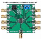
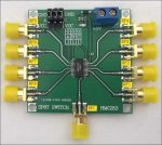
I was wondering if any one was using one of the 8 position antenna switches from AlieExpres?

/www.aliexpress.com/item/1005002120003412.html?spm=a2g0s.8937460.0.0.816c2e0ePgpkbr

1630635393979.png
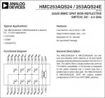
I bought one and have been playing with it a bit. I do like it although I have found a discrepancy between the chip and the way it is working. The chip diagram has all switch positions open when not engaged, no power. In reality all switches go closed connecting all ports when power is removed.
I think I can use this to some advantage for static discharge protection if I ground one of the antenna leads through a resistor to ground. All ports have a capacitor to isolate it from DC so the grounded port would only help with an impulse such as a near lightning discharge.
After a recent near lightning strike taking out some of my equipment. I have decided to upgrade my now non existent lightning protection. My old method of just unhooking it only works as well as a my memory.
For now I plan on putting the switch near my outside antenna collection point to eliminate several coaxial runs.
I have ordered a couple of the
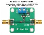
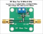
DC Bias 10-6000MHz 6GHz RF Tee Broadband Microwave DC Bias Blocker

DC Bias 10-6000MHz 6GHz RF Tee Broadband Microwave DC Bias Blocker from AlieExpres
The way I plan on providing a DC ground for the antennas is to put one of the biasT on the input line of the antenna switch with the DC+RF side connected to the 8 position switch. The biasT power connector will then be grounded. a blocking capacitor is in line before going on to the radio.
Joe
 

rabbit108

Member
Joined
Jan 4, 2021
Messages
329
Location
S.E. VA
I was wondering if any one was using one of the 8 position antenna switches from AlieExpres?

The way I plan on providing a DC ground for the antennas is to put one of the biasT on the input line of the antenna switch with the DC+RF side connected to the 8 position switch. The biasT power connector will then be grounded. a blocking capacitor is in line before going on to the radio.
Interesting devices for a difficult problem.

RF Switch HMC253_8 ports SMA connectors_1.jpg

RF Bias Tee_1.jpg

I lost a computer from a close strike. The computer was off, it was plugged into a surge suppressor strip that was also off, but the strip was still plugged into the wall receptacle.
A 20" SONY TV in the living room had a CRT with weird colors. The EMP from the strike had magnetized the shadow mask. I turned TV off and then on. I heard the normal "thunk" sound of the degaussing coil; the colors were then OK.

I now unplug my computer suppressor strip in bad weather.

Hams on Field Day sometimes lose the front end of their receivers from static build up on the antenna. Sometimes a resistor or RF choke to ground can help.

Antennas that have a design with an inherent DC ground will drain any static build up.

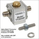
You might consider a gas tube device that will shunt an impulse to ground.

TII Coax Surge Protector4_1.jpg
 

ka9ucn

Member
Joined
Dec 23, 2016
Messages
33
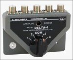
The Alpha Delta antenna switch is a very well built high quality switch but it will not fit into my plans.
I plan on using the 8 position switch in a remote switching network to allow less coax runs into the house. I have around another 30 to 60 days before there will be any new SDR radios will be put into service. This will give me time to redo the antenna system. For now the plan is a metal box at the bottom of a personally owned telephone pole. It will contain a LNA, antenna switch, lightning protection, filters and a dedicated well filtered battery backed up DC power supply. I have no intentions of using any of this antenna network for transmitting at this time.

Joe
 

rabbit108

Member
Joined
Jan 4, 2021
Messages
329
Location
S.E. VA
The way I plan on providing a DC ground for the antennas is to put one of the biasT on the input line of the antenna switch with the DC+RF side connected to the 8 position switch. The biasT power connector will then be grounded. a blocking capacitor is in line before going on to the radio.

RF Bias Tee_2.jpg

What is between the DC+RF side and the grounded power connector? It's usually a choke in a BiasT. I see what looks like 2 capacitors to ground, but they will be shorted to ground.
 
Last edited:

ka9ucn

Member
Joined
Dec 23, 2016
Messages
33
1630814292450.png I plan on placing the DC block in the reverse of what it is usually thought. It will not to be used to send and separate a DC controls voltage down the coax. Instead the DC will be on the antenna side and then grounded. The signal will then pass through the pass capacitor on the PCB and go on to be treated as any other signal. The DC block would appear to have two capacitors one inductor and one rectifier in the DC supply chain. For my plan to work I will either reverse the rectifier. In witch case I am very concerned with rectifier switching noise or simply replace it with a low ohm resistor.
I checked the tracking and should be getting the new DC block biasT boards within the next week. When it comes in I will be more able to evaluate it and if I can just reverse the rectifier if that is what it appears to be or if I will have to replace it with a low ohm resistor.
Yes it appears there are two capacitors. They are on the DC side of the choke so as to not affect the signal. They are used to decouple any rf that might have made it through the choke.

Joe
 

ka9ucn

Member
Joined
Dec 23, 2016
Messages
33
View attachment 109041 I plan on placing the DC block in the reverse of what it is usually thought. It will not to be used to send and separate a DC controls voltage down the coax. Instead the DC will be on the antenna side and then grounded. The signal will then pass through the pass capacitor on the PCB and go on to be treated as any other signal. The DC block would appear to have two capacitors one inductor and one rectifier in the DC supply chain. For my plan to work I will either reverse the rectifier. In witch case I am very concerned with rectifier switching noise or simply replace it with a low ohm resistor.
I checked the tracking and should be getting the new DC block biasT boards within the next week. When it comes in I will be more able to evaluate it and if I can just reverse the rectifier if that is what it appears to be or if I will have to replace it with a low ohm resistor.
Yes it appears there are two capacitors. They are on the DC side of the choke so as to not affect the signal. They are used to decouple any rf that might have made it through the choke.

Joe
antenna.png
 

rabbit108

Member
Joined
Jan 4, 2021
Messages
329
Location
S.E. VA
View attachment 109041 I plan on placing the DC block in the reverse of what it is usually thought. It will not to be used to send and separate a DC controls voltage down the coax. Instead the DC will be on the antenna side and then grounded. The signal will then pass through the pass capacitor on the PCB and go on to be treated as any other signal.
That should work.
 

rabbit108

Member
Joined
Jan 4, 2021
Messages
329
Location
S.E. VA
Thank you for the new attachment, Joe; I couldn't make out the tiny image.

ka9ucnRadioRefAntSwitch_1.png

Good to see you have added gas discharge tube to protect your RCVR. The DC ground provided by the Bias Tee probably would not catch transients.

I was wondering about the switching control. I didn't see any details about that in your listing for the switch. Is that very difficult? However, I did find a listing that shows the application note and 2 negative reviews. Those guys probably couldn't figure how to control the switch.


RF Switch HMC253_8 ports SMA connectors2_1.jpg

Data Sheet:
https://www.analog.com/media/en/technical-documentation/data-sheets/hmc253aqs24.pdf

RF Switch HMC253 Application1_1.jpg

RF Switch HMC253 Application2_1.jpg

The data sheet says:
NOTE: DC Blocking capacitors are required at ports RFC and RF1, 2, 3, 4, 5, 6, 7, 8.
Is that a problem? It looks like they are already on the board.
 
Last edited:

ka9ucn

Member
Joined
Dec 23, 2016
Messages
33
I did not realize that I hap put the picture as a thumb nail. I apologize.
You are right. The capacitors are on the board
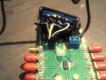
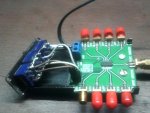
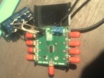
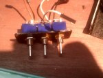
I used 3 double pull double throw, 3 single pole double throw would have worked just as well.
On the PCB the 3 pins near the edge are at ground potential. “0"
The center 3 pins labeled ABC are shorted to ground “0" or “1"=5VDC logic high.
The row farthest from the edge marked VCC is at 5 VDC logic high “1".
The switches are then binary counting from 0 to 7.
The board would not take a big hit before damage. I plan on using it as a static ground.
This is just the first test. If all goes as expected I plan on putting one on each antenna to directly discharge any static build up on the antenna wire.
As I have it now with the blocking capacitors between the 8 position switch and DC block, will only bleed off the line between the two PCBs in the hopes that this will help keep the voltage below the trigger voltage of the Gas discharge tube. It is just a start but it is a start.
JoeDSCF0037.JPGDSCF0043.JPGDSCF0045.JPGDSCF0047.JPG
 

Ubbe

Member
Joined
Sep 8, 2006
Messages
9,047
Location
Stockholm, Sweden
There's lots of $3 BCD switches that would make the user interface a lot easier.

s-l500.jpg


1set Thumbwheel BCD Switch 1-Digit + Cap TF51 GTF511221 0~9 Scale H=18mm Hampolt | eBay

/Ubbe
 

ka9ucn

Member
Joined
Dec 23, 2016
Messages
33
A binary switch would work great and simplify things!
I did not have one on hand and I did have a drawer full of the toggle switches so I used what I had. I will order some from AlieExpress.
The one suggested from Ebay. The cost is very good at $3.10 but $12.50 for shipping?

Joe
 

BackHive67

Member
Joined
Oct 9, 2014
Messages
26
Location
Dublin, Ireland.
I'm very interested in a way to ground my Shortwave/HF antennas that I have connected to my own HMC252 (6 way) board (from Aliexpress also). I'm currently on my second board and now, I have some replacement HMC252 ICs en-route (I'm gonna replace the IC this time, rather than the entire board). I have found that after some time, some of the 6 input channels become locked open.. I expect static build up has damaged that channel of the IC. As mentioned above, each of the inputs go closed when power is removed from the board, so I expect it happened then.

The second (replacement) board I installed only 3 weeks ago now only has two channels usable. I have a 9:1 longwire antenna connected to Channel 1 and it died a few days ago. I have a Mini-Whip and a Loop antenna on 4 and 5. Channels 2, 3 and 6 were dead on arrival from China !!

When I replace the IC on the current board, I plan on soldering a gas discharge tube device on each input (between the centre pin of each SMA connector and ground). Of course, I will also properly ground the PCB.

Does anybody have any better ideas to ground the inputs and the PCB ?

Terry
 
Status
Not open for further replies.
Top