Copper off center antenna question

Status
Not open for further replies.

Medic42

Member
Joined
Jul 5, 2007
Messages
6
Location
Canton, SD
I built the copper off center scanner antenna. 18 inches and 48 inches copper tubing cut. 18 in part cover vhf and 48 in part cover uhf or vice versa? Thanks
 

Attachments

  • 4A471C3F-2BEB-44B9-9A63-05326C3537A2.jpeg
    4A471C3F-2BEB-44B9-9A63-05326C3537A2.jpeg
    15.1 KB · Views: 321

prcguy

Member
Joined
Jun 30, 2006
Messages
15,336
Location
So Cal - Richardson, TX - Tewksbury, MA
What you have is an antenna that resonates around 85MHz as a half wave and will also work on a few even and odd harmonics like the 2nd at 170Mhz, 3rd at 255Mhz and 4th at 340MHz and 5th at 425MHz and so on. The feedpoint impedance on all those bands is around a couple hundred ohms and the TV transformer helps match to 75 ohm coax.

You could tune the antenna so the half wave resonance is around 77.5MHz, then it should light up in slightly more useful areas like 155Mhz, 232.5 MHz, 310MHz, 387.5MHz, 465MHz and at some point 775MHz and 852.5MHz. But if this antenna is set up vertically it will have a good radiation pattern at the horizon only at 77.5MHz and everywhere else it will be pointing up to the sky or down at the ground with more and more lobes as you go higher in frequency. Pretty bad for a scanner antenna in my opinion.

I don't understand why anyone would bother to make one for scanner use as its an offshoot of a much larger HF amateur antenna that is used horizontally where you can live with the lobes easier.

None


I built the copper off center scanner antenna. 18 inches and 48 inches copper tubing cut. 18 in part cover vhf and 48 in part cover uhf or vice versa? Thanks
 

nanZor

Active Member
Joined
May 28, 2009
Messages
2,807
I don't understand why anyone would bother to make one for scanner use as its an offshoot of a much larger HF amateur antenna that is used horizontally where you can live with the lobes easier.

Good evaluation of the antenna. And taken by itself, it doesn't seem to make any sense. It's one reason you never see any of these on a hilltop. :)

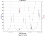
But from a consumer scanner-front end standpoint (generally poor, especially if using a handheld), prone to overload and desense, in high signal areas, the non-ideal lobes provide a certain amount of attenuation on their own above VHF which may cut down on having to use programmable attenuators.

Back in the day when this was conceived, with the pro-2006 front-end being the standout exception, yet STILL, this provided much better reception than the included whip screwed into the top. It helped lesser scanners, especially those without programmable attenuators, mainly for 800mhz overload, even more.

So from a *consumer systems standpoint*, the reasons to build one might be:

1) Far better than a back-of-set antenna.
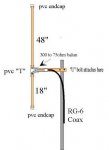
2) Indoor versions can use wires attached to the transformer instead of tubing.
3) Low parts-count, quick build time, and non-critical project assembly.
4) The bang-per-buck is high - despite the antenna not being purely ideal on it's own.
5) Takes up minimal space in the garbage can if one is not happy with it.

But don't put makeup on a pig. Only take it so far, which is generally a quickie non-optimal installation to a receiver or handheld with a poor front end.

For those starting to DIY, it can be a confidence-building first stepping stone to something more specific and higher in performance.
 
Last edited by a moderator:

popnokick

Member
Premium Subscriber
Joined
Mar 21, 2004
Messages
2,840
Location
Northeast PA
I have found to my surprise that both of my Off-Center Dipole scanner antennas (wire version and copper pipe version in the attic) work well in the VHF Low band (30-50mHz)... well below the natural resonance of 85 (or 77.5 mHz). This is likely due to the 75 ohm coax feed line becoming part of the total length of the antenna in the lower VHF range. In the VHF High band I regularly receive the mountaintop transmitter of a neighboring state's police dvision which is 75 air miles distant over mountains to the north, as well as VHF and some UHF transmissions from NYC.... about 75 miles southeast.... as well as countless civilian and military air transmissions (including an ARTCC remote base transmitter). All in all.... not bad for less than $20 in parts from any home / hardware store and about 20 mins of my time. This is in addition to the dozens of favorable price vs. performance reports found here on RR for this antenna.
 
Last edited:

Ubbe

Member
Joined
Sep 8, 2006
Messages
9,033
Location
Stockholm, Sweden
I have a 155MHz GP antenna sitting next to me and if I sweep it below it's tuned frequency it at one point begins to match up pretty good again, at 90MHz. It's not a dipole but you would expect your antenna to start to work again at the lower bands, just as you have experianced.

/Ubbe
 

Attachments

  • GP155MHz sweep.jpg
    GP155MHz sweep.jpg
    66 KB · Views: 145

nanZor

Active Member
Joined
May 28, 2009
Messages
2,807
As popnokick points out, we are using some of the *faults* of an ordinary system to sneak in some function, such as using the common-mode for VHF-low.

Or using the normally undesirable high-angle lobes on UHF and above to become natural attenuators for cheap scanner front ends.

There is another fault to be well aware of - at its primary resonant frequency near the FM broadcast band, this can be an invitation to desense and overload with lesser front-ends, especially those without good bandpass filters.

If you live near an FM broadcast flamethrower, you may want to add an inexpensive fm-trap inline. Ok.

But if you feel the need to run hardline and cavities to this thing, that is a red-flag that you are putting lipstick on the pig! :)
 
Status
Not open for further replies.
Top