I have been building an AM radio, and when powered on I was picking up what id presume to be radio waves (what I'd describe as a mishmash of "whooshing" sporadic oscillations).
Alright all items for this project are the following:

x1 MAX4026EWP+T op amp IC chip
x2 1000 microfarad capacitors (any capacitor works but it's louder with these)
x1 100 microfarad capacitor
x1 8 ohm speaker
x1 9 volt battery
x1 project board
some wire (I used about a foot and a half)
optional - a wire parabola (such as a mini fan cage, a colander, etc.)

Simply put this circuit doesn't take much to make. It surprised and annoyed me because it gave me a radio signal when I was trying to make a backpack boombox circuit, so I fiddled with this and I present it to you here. And here are the 4 steps to creating this circuit.
(Please realize that when I talk about the pins I refer to the pins in counter-clockwise order from the clocking mark (probably an indent or circular mark at one end of the chip near pin 1. Pin 1 is the most counter-clockwise going down the left side to pin 4 and continuing at the bottom of the other side at pin 5 going up the right side to pin 8.)
1. Plug in your op amp and add a jumper wire from pin 6 to power and a jumper from pin 4 to ground.
2. Plug another jumper wire from pin 2 to ground and plug your antenna into pin 3.
3. Plug your 100 microfarad capacitor's positive side into ping 7 and the negative side into ground. Plug one your 1000 microfarad capacitor's positive side into pin 1 and the negative side into pin 8. The other 1000 microfarad capacitor's positive side into pin 5 and the negative side into a blank space on your board. Plug your speaker's positive side to the last capacitor's negative side and the negative side of your speaker to ground.
4. Plug in your battery's terminals to their respective rails (red to power, black to ground)
and then (if you have a switch added) turn it on and simply move your antenna wire around to get your signals. If you want a good signal using a metal fan cage works very well.
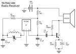
This was great, but I wanted to single out a specific frequency and listen to a radio station. I did some research and figured out that I have to add a resonance circuit called an LC circuit to single out specific frequencies. I made one with a variable inductor I made with 47 coils in 10cm with square steel railroad spike of diameter 1.5 cm in the center and a capacitor like below. I experimented with 220 pF capacitors in parallel to make 220, 440, and 660 pF and tried using my variable inductor to tune into a station for each of them but it did not work.
schematic with added tuner (apologize for the poor drawing)
I chose that coil count using the following equation to tune into mid freq radio singles (535-1500 khz), I made sure it covered the lowest frequency and then I could shorten it to get the higher frequencies.:
lc circuit equation
At this point I was stumped, I heard that you had to put a diode in to single out high frequency singles so desperate, I inserted it between pin 3 and my LC circuit but it didn't help. I also made a home made variable capacitor but likewise I coundn't tune into a station. Most importantly I heard you had to ground the circuit so I attached a wire for the tuner circuit to my computer(which is ground) and it changed the tone slightly but still couldn't tune into a station.
I started to wonder whether there were any am stations in my area due to its falling popularity, but a quick test with my mother's car radio yielded handful of them.
I apologize if my troubleshooting may seem stupid but I'm a little new to this circuit building stuff. I Thank you for reading thus far, and I appreciate any assistance you guys may offer.
Alright all items for this project are the following:
x1 MAX4026EWP+T op amp IC chip
x2 1000 microfarad capacitors (any capacitor works but it's louder with these)
x1 100 microfarad capacitor
x1 8 ohm speaker
x1 9 volt battery
x1 project board
some wire (I used about a foot and a half)
optional - a wire parabola (such as a mini fan cage, a colander, etc.)
Simply put this circuit doesn't take much to make. It surprised and annoyed me because it gave me a radio signal when I was trying to make a backpack boombox circuit, so I fiddled with this and I present it to you here. And here are the 4 steps to creating this circuit.
(Please realize that when I talk about the pins I refer to the pins in counter-clockwise order from the clocking mark (probably an indent or circular mark at one end of the chip near pin 1. Pin 1 is the most counter-clockwise going down the left side to pin 4 and continuing at the bottom of the other side at pin 5 going up the right side to pin 8.)
1. Plug in your op amp and add a jumper wire from pin 6 to power and a jumper from pin 4 to ground.
2. Plug another jumper wire from pin 2 to ground and plug your antenna into pin 3.
3. Plug your 100 microfarad capacitor's positive side into ping 7 and the negative side into ground. Plug one your 1000 microfarad capacitor's positive side into pin 1 and the negative side into pin 8. The other 1000 microfarad capacitor's positive side into pin 5 and the negative side into a blank space on your board. Plug your speaker's positive side to the last capacitor's negative side and the negative side of your speaker to ground.
4. Plug in your battery's terminals to their respective rails (red to power, black to ground)
and then (if you have a switch added) turn it on and simply move your antenna wire around to get your signals. If you want a good signal using a metal fan cage works very well.
This was great, but I wanted to single out a specific frequency and listen to a radio station. I did some research and figured out that I have to add a resonance circuit called an LC circuit to single out specific frequencies. I made one with a variable inductor I made with 47 coils in 10cm with square steel railroad spike of diameter 1.5 cm in the center and a capacitor like below. I experimented with 220 pF capacitors in parallel to make 220, 440, and 660 pF and tried using my variable inductor to tune into a station for each of them but it did not work.
schematic with added tuner (apologize for the poor drawing)
I chose that coil count using the following equation to tune into mid freq radio singles (535-1500 khz), I made sure it covered the lowest frequency and then I could shorten it to get the higher frequencies.:
lc circuit equation
At this point I was stumped, I heard that you had to put a diode in to single out high frequency singles so desperate, I inserted it between pin 3 and my LC circuit but it didn't help. I also made a home made variable capacitor but likewise I coundn't tune into a station. Most importantly I heard you had to ground the circuit so I attached a wire for the tuner circuit to my computer(which is ground) and it changed the tone slightly but still couldn't tune into a station.
I started to wonder whether there were any am stations in my area due to its falling popularity, but a quick test with my mother's car radio yielded handful of them.
I apologize if my troubleshooting may seem stupid but I'm a little new to this circuit building stuff. I Thank you for reading thus far, and I appreciate any assistance you guys may offer.
") )
)