DYI Scanner antenna

Status
Not open for further replies.

nated1992

Member
Joined
Feb 9, 2013
Messages
271
Location
Asheville NC
So i have recently experimented with making my own antenna, I believe i have been pretty successful in my creations with the average reception ranging for 20-40 miles, Even more impressive due to the fact i live in a mountainous region.

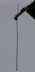
1 I used a aluminum tube and some coax, I toke about 10 inches of the coax striped down to the copper conducting wire and coiled it, Then inserted it into the aluminum tube until it reached the other end ( Which was capped ) I then sealed the end which had the shielded coax exiting and placed a F connector on the end.

The 2nd i used some scrap parts of some other antennas and it turned out well although want really "Home Made"

Any thoughts or ideas on ways to make antennas which get maximum reception?

Examples of your DIY Antennas would be neat!

I will try to get some pictures of mine and share!

Thanks for the input!
 

ladn

Explorer of the Frequency Spectrum
Premium Subscriber
Joined
Oct 25, 2008
Messages
1,309
Location
Southern California and sometimes Owens Valley
I've had excellent luck with designs based on the OCF dipole scanner antenna presented on the RR Wicki:

Homebrewed Off-Center Fed Dipole - The RadioReference Wiki

I've made several versions. My first one was made out of aluminum tubing; the others were made from RG 174 coax (center conductor and braid tied together). The RG 174 antennas are great for field/portable use.
 

nated1992

Member
Joined
Feb 9, 2013
Messages
271
Location
Asheville NC
I now plan on giving that a try!

My I ask what is the importance of connecting the braided shielding to a element?
I did not do so in my attempts and can't help but wonder if it hurt performance
 

mark40

Member
Premium Subscriber
Joined
Aug 18, 2007
Messages
255
Location
Pike County, Pennsylvania
Attached two photos:
The two home brew antennas are mounted to the side of the house facing West. The vertical dipole is cut for 460 MHz. Set this one up to monitor Monroe County PA west of my location coupled to a BC350C. The horizontal dipole is for FM broadcast coupled to an old Lafayette table top radio.

The coax is soldered to ground wire I cut out of some unused romex cable; inserted into 3/4PVC pipe and capped at the ends. Painted the antenna and cable to match the house.

The other photo is of my Grove Omni which is just like the OCF dipole featured here. Obviously Mr. Grove thought highly of the design
 

Attachments

  • PC240025.jpg
    PC240025.jpg
    34.9 KB · Views: 2,046
  • PC240026.jpg
    PC240026.jpg
    8 KB · Views: 2,078
Last edited:

mark40

Member
Premium Subscriber
Joined
Aug 18, 2007
Messages
255
Location
Pike County, Pennsylvania
I went back to a ARRL article I used to learn about building my dipole, it states:

"A dipole gets it's name from two halves - one on each side of it's center (In contrast, a monopole has a single element, usually fed against ground as a vertical) A dipole is a balanced antenna, meaning the "poles" are symmetrical: They're equal in length and extend in opposite directions from the feed point".

So from that description it sounds like you may have a monopole?

http://www.arrl.org/files/file/Technology/tis/info/pdf/9106023.pdf
 
Last edited:

popnokick

Member
Premium Subscriber
Joined
Mar 21, 2004
Messages
2,840
Location
Northeast PA
ladn wrote: "the others were made from RG 174 coax (center conductor and braid tied together" and nated1992 asked, "May I ask what is the importance of connecting the braided shielding to a element?".
I think what ladn meant is that when he made his OCFD antenna he shorted the braid and center conductor together to make a single electrical conductor for each "leg" of the OCFD. So there would be a 48" piece of "shorted" RG-174 for one leg, and an 18" shorted piece of RG-174 for the other leg of the OCFD. Having a greater diameter element for each leg of the antenna increases the effective bandwidth of the antenna, which is why the copper pipe version of the OCFD is more broad banded than the wire version. Shorting RG-174 coax for each leg "puts more metal" into each element.
 
Last edited:

nated1992

Member
Joined
Feb 9, 2013
Messages
271
Location
Asheville NC
I do have a monopole antennae however i missed a step in my construction which is the ground plate or radials, However this should be a easy fix when i switch towers,

Thanks for all the great answers and getting me pointed in the right direction!

So here is another!

Is there a diffrence in reception with a dipole and a monopole
 

LtDoc

Member
Joined
Dec 4, 2006
Messages
2,145
Location
Oklahoma
"Is there a diffrence in reception with a dipole and a monopole"
Yes there certainly can be, and is typically related to polarization. Most dipoles are mounted horizontally, not always but maybe half the time. A monopole is typically mounted vertically. That's more a factor at HF rather than VHF/UHF because of the size of the two at those frequencies. At VHF/HF directivity also comes into play. A horizontally mounted dipole is a bidirectional antenna, sort of, with 'nulls' tending to be off the 'ends' of it. Turn that vertical monopole sideways and it would also be bidirectional with nulls off it's ends too.
So, yes there can be a difference between those 'types' of antennas. How much difference has to be 'tried' to find out.
- 'Doc
 

popnokick

Member
Premium Subscriber
Joined
Mar 21, 2004
Messages
2,840
Location
Northeast PA
"Would a dipole be effective for broad range scanning?" Not particularly, because a dipole is resonant for a particular frequency (and harmonic multiples in many cases). However, the special case of an Off-Center Fed Dipole (OCFD) is EXTREMELY "broad range" in terms of its frequency coverage. In particular, the versions described in the RR Antenna Wiki are designed to be effective from 30 mHz up to 800 mHz (with some pattern distortion at the high end). There are many, many threads here on RR discussing the OCFD antenna for scanning.... with most commenting how well it works across a broad range of frequencies for the price and simplicity. At the VHF low band end of the range it actually uses the coaxial cable as part of the antenna. The following thread is one of many discussing the OCFD's broad frequency range, despite its native resonance at about 88 mHz:
http://forums.radioreference.com/build-your-own-antenna/268033-homebrewed-ocfd-pics-question.html
 

ladn

Explorer of the Frequency Spectrum
Premium Subscriber
Joined
Oct 25, 2008
Messages
1,309
Location
Southern California and sometimes Owens Valley
I now plan on giving that a try!

My I ask what is the importance of connecting the braided shielding to a element?
I did not do so in my attempts and can't help but wonder if it hurt performance

Since I was using coaxial cable for the antenna elements, I wanted them to perform as if I were using just plain regular stranded wire. The coax feedline should not be shorted out.

These are the best base/portable scanner antennas I've ever used for general purpose scanning (Los Angeles area). If we had more agencies on VHF lowband, I'd reconfigure to get a little better performance there to receive mobile units. As it is now, the only lowband I monitor is California Highway Patrol and then only the repeater outputs/base frequency and a few of the car-to-car simplex channels.
 

nated1992

Member
Joined
Feb 9, 2013
Messages
271
Location
Asheville NC
So i have played with different configurations on the line running to the antenna, I have found that a power injector with no Amp gets the best results!

I also toke down the antenna and added the Ground Elements

Currently I have a 30-50 mile range with the tip of the antenna at about 30 feet off the ground, ( About a foot over the ridge of the roof ) For the most part all is crystal clear with some static on occasion.

Still interested in learning about Antenna making and getting some more going!
 
Status
Not open for further replies.
Top