Half-wave coaxial "flowerpot" vertical

Status
Not open for further replies.

nanZor

Active Member
Joined
May 28, 2009
Messages
2,807
Thanks to a tip from Boatanchor, I built my own airband half-wave dipole following the instructions here from VK2ZOI who built amateur-band versions:

Half-Wave Flower Pot Antenna – VK2ZOI

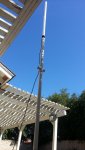
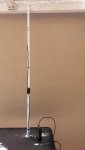
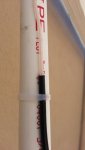
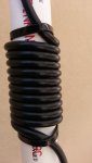
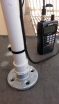
For VHF airband, I used 1-inch pvc, 8 turns of rg-58, and about 20-inches for each element length. Finishing touch included wiping down the pvc and coax coil with Armor-All protectant. At first I just tie-wrapped it all up, and then put it inside without too much detuning.

No, it isn't a hard-core sleeve dipole. But, I found the instructions convenient and appreciated the scaling charts for frequencies other than amateur bands. In this case, the choke's self-resonance is purposely tuned a bit lower than the desired center frequency of the dipole itself.

VHF coax chokes work to an extent if the diameter is kept small, and you don't wind too many or too little amount of turns.

I did nearly the same thing awhile back with nothing but #43 ferrites as a choke, but found that this simple antenna is easy to build and reasonable in performance. Certainly much more than the old "just fold back the braid" technique. :)

Thanks again Boatanchor for the heads up on this.
 

nanZor

Active Member
Joined
May 28, 2009
Messages
2,807
Works great. Instead of the base being jammed into a flowerpot for stealth reasons, I just bought two 5-foot pre-cut lengths of 1-inch pvc, and a coupler. One length is for the antenna itself, and the other length is just to get some height. I placed it on a microphone stand for temporary testing.

Electrically, it is just half-wave vertical dipole, although the bottom half relies upon the common-mode of the coax, which has to eventually be choked off to some extent. I used RG-58 since it has a solid dielectric that can withstand a 1-inch bend radius. I would NOT use foam dielectric coax as eventually the center conductor will migrate with such tight bends.

The top half of the coax has the black outer sheath and the braid stripped away, yet I left the inner dielectric surrounding the center conductor intact. 20 inches below that is just another 20 inches of coax with nothing stripped, immediately followed by the choking coil. A little piece of heat-shrink or even just tape for real temporary use is wrapped around the feedpoint at the end where the sheath and braid was stripped away to cut down on on moisture migration into the coax braid.

I had a few 20 and 50 foot Radio Shack RG-58 jumpers with SO-239 connectors laying around, so I cut one up, made the antenna, and used an adapter to mate with my scanners.

I found that placing it into the pipe didn't severely detune the antenna, as it was already pretty well covered by the insulating inner dielectric and coax sheath anyway, so I applied a 0.9 velocity factor to my quarter wave calculations for the element lengths and got into the ballpark. Since we're not using the coax in any sort of transmission line mode for the antenna, just the common mode, the typical coax velocity factor of .66 is NOT applicable here. Just enough to compensate for the dielectric covering, so 0.85 to 0.9 seems to be fine, ie:

234 / 128 mhz = 1.828 feet = 21.936 inches each side.

21.936 * .9 vf = 19.742 inches each side with vf compensation. 20 inches was good enough, and left me with a little room to cut down if I really wanted to try and perfect it.

Purists will find a little bit of common-mode interaction below the choking coil as this type of choke only goes so far, but in practice is FAR better than the old "just fold down the braid" dipoles, as long as you get close to a bit below the bottom of the band you are making it for when consulting the turns chart.
 

Attachments

  • flowerpot_ant.jpg
    flowerpot_ant.jpg
    48.5 KB · Views: 6,608
Last edited by a moderator:

Rt169Radio

Member
Premium Subscriber
Joined
Aug 24, 2011
Messages
2,960
Location
CT
Nice project. It is always cool to see a homemade antenna.
 

nanZor

Active Member
Joined
May 28, 2009
Messages
2,807
Additional note: the coax I used already had a connector on the end, and I was too lazy to chop it off. Even though I drilled two holes for the coil, it was a real pain to try to thread the coax through the bottom and out through the bottom hole.

So, I just threaded the actual antenna part inside the tube through the top hole, and secured it at the end. Then wound the coil, but the connector is way too large for the bottom hole so I just left the coax beneath the coil on the outside too.

If you don't want to drill any holes whatsoever, and can deal with it being exposed (the coil already is anyway), you could just mount the whole thing outside the pipe. The detuning affect is already swamped by the inner dielectric and coax sheath of the antenna part anyway, so placing it inside the tube didn't show much of a difference in resonance. Just apply a .85 to .9 velocity-factor multiplication factor to your element length calculations and you'll be in the ballpark as long as you leave the exposed inner dielectric surrounding the center conductor.

Taking it a step further for portable use, one could just use a few inches of pvc for the coil form, and then hang the rest from an overhead support.
 
Last edited by a moderator:

Boatanchor

Member
Joined
Jul 17, 2011
Messages
991
All great ideas :)
These really are a fun, cheap but very effective antenna to build.
 

nanZor

Active Member
Joined
May 28, 2009
Messages
2,807
Portable version

Some more detailed info. The stealth-mount flowerpot has been excluded.

This one is semi-portable. All the wiring is tie-wrapped on the outside and the Schedule-40 pvc 3/4 inch is just used as a support. Missing from the photo is an end-cap or plug to keep moisture out.

Later on, I cut a few inches of pvc off the bottom below the coil to shorten it up a little so I don't break windows indoors. :) Coil is now only about a foot higher than the base.
 

Attachments

  • portant1.jpg
    portant1.jpg
    25.9 KB · Views: 8,759
Last edited by a moderator:

nanZor

Active Member
Joined
May 28, 2009
Messages
2,807
For vhf airband, the black covering and braid of the RG-58 has been stripped away for 20 inches, leaving the inner dielectric over the center conductor. I used a Radio Shack 12 foot RG-58 bnc-connectorized jumper #278-965 and just cut one connector off.

This is the feedpoint of the center fed dipole. Apply some sealant to this area as the coax braid will wick moisture from the air.
 

Attachments

  • portant4.jpg
    portant4.jpg
    20.5 KB · Views: 5,984
Last edited by a moderator:

nanZor

Active Member
Joined
May 28, 2009
Messages
2,807
This is the RF-choke. It was wound according to the VK2ZOI charts for a little bit below the the bottom of the airband, NOT right at the desired center frequency. Here I'm using 11 full turns, and the entry / exit points of the choke are aligned with each other more or less. See below for other band sizing/winding info.

Note that in his charts, metric pvc sizes are always the OD outer-diameter. His charts correspond roughly to 3/4-inch, 1-inch, and 1-1/2 inch US pvc OD dimensions.
 

Attachments

  • portant3.jpg
    portant3.jpg
    27 KB · Views: 7,398
Last edited by a moderator:

nanZor

Active Member
Joined
May 28, 2009
Messages
2,807
A quickie portable mount here consists of a 1/2-inch galvanized pipe flange, a 1/2-inch to 3/4-inch "extender", and then about 5 feet of 3/4-inch pvc mast. Heavy winds will snap the threads of the extender unless you guy it.

Another alternative is to use a heavy portable desk mic-stand, like the Radio Shack #33-370 where you just slip the pvc over it.
 

Attachments

  • portant2.jpg
    portant2.jpg
    47.9 KB · Views: 6,107
Last edited by a moderator:

nanZor

Active Member
Joined
May 28, 2009
Messages
2,807
Quickie RG-58 antenna sizing and coil winding info for 3/4-inch schedule 40 pvc:

VHF airband 118 - 136 mhz
Each "element" of the dipole should be 20 inches long. (total length 40 inches before hitting the choke)
Choke coil of 11 turns.

Amateur 2m 146 mhz
Each element 18 inches
Choke coil 9 turns

Business 153 mhz
Each element 17 inches
Choke coil 8 turns

Railroad / Marine 160 mhz
Each element 16 inches
Choke coil 7 turns
 
Last edited by a moderator:

nanZor

Active Member
Joined
May 28, 2009
Messages
2,807
I've certainly had fun with them considering what they are.

If I had to, I'd put them in somewhat the same performance class as another half-wave antenna - the J-pole (although the J is end-fed through a quarter wave transmission line) - that doesn't have the best of common-mode current control either.

I'll bet that if one were to put these on a test-range, you'd see the rough equivalent performance to a quarter-wave ground plane antenna. The slight amount of common mode current on this antenna tends to raise the elevation angle.

But I don't want to sell this thing short - it is much easier to hide / mount in a flowerpot, and if that is what it takes to get it up and outside, then worrying about common-mode current can come much later. :)
 

nanZor

Active Member
Joined
May 28, 2009
Messages
2,807
Added another coil

Since I had enough pvc mast, I wound another coil a quarter-wave away from the bottom of the first one. In this case, another 11-turn coil was started 20 inches away for my airband monitoring. (remembering that the black coax covering has about a .9 vf, so that's why it is 20 inches, and not longer for airband).

I have a weak low-level ATIS nearby, and the signal peaked up just barely. On an Icom R20 S-meter, I got just one more little bar out of it. So it seems that the secondary coil may have attenuated the common mode a bit more, and brought the elevation angle down just a tad.

I think if you have the extra cable and pvc, it is worth it to wind a secondary coil a quarter-wave away from the first.
 
Last edited by a moderator:

TeRayCodA

Member
Joined
Jan 1, 2005
Messages
457
Location
Muskogee,Oklahoma
Love it! I built this one a few years ago.Aircraft( Mil air/civilian Air) is superb! This thing took a lot of time to build!! but it's my favorite!
 

Attachments

  • IMG_0067.jpg
    IMG_0067.jpg
    49.6 KB · Views: 6,754

nanZor

Active Member
Joined
May 28, 2009
Messages
2,807
The importance of the second choke!

You SHOULD be proud of that discone - I especially like the added elements for more density to get closer to replicating a real cone and solid disk. It may be hard to pop into a flowerpot for stealth reasons like these resonant feed dipoles. :)

How to fix the resonant feed dipole:

Now that I've seen this thing scaled down with TWO chokes, it suddenly bacame apparent why amateurs who use these things on the HF bands are usually not happy overall with the "choking" action of the coax coil, along with the weird lobes associated with plenty of common-mode current on the braid.

The first "choke" is not a choke at all, but merely an LC resonant circuit to establish the lower dipole boundary, but does not do much for common-mode current below the coil. The reason for this is that the end of a dipole with a coax coil is in a low-current / high-voltage node. Any choke placed a quarter-wave away from the feedpoint, be it a resistive ferrite, or a reactive coil choke will be ineffective here. So to my thinking, the first choke is really just a tuned circuit.

This tuned circuit does however tame the system somewhat from being just a quarter-wave spike with a random length coax braid as the other side of the dipole.

The second coil choke, placed a quarter-wave lower than the first coil, actually DOES perform like a choke, since it is at a high-current / low-voltage node instead. There is a limit to the effectiveness of reactive vs resistive chokes, but at least from the standpoint of "I don't have any ferrites and all I have is coax" environment, the second coil of coax really seems to help.

Note that measuring common-mode choking by the "hand capacitance" method is not a guarantee. AND, you can have out of phase choking added to the mix. But the second choke I added does not seem to degrade my reception, and in fact improves it somewhat. I just wish I had better equipment to get some real data from it, and not provide just an empirical opinion.
 
Last edited by a moderator:

Rastaman147

Member
Premium Subscriber
Joined
Nov 22, 2012
Messages
69
Location
Carlisle, PA
Hertzian, how much power will the flower pot antenna handle?

Hertzian,

I built the 5/8 VHF - UHF dual band version of this antenna a few weeks ago to use with my HT, and it works great! I've also tried connecting my scanner to it, and it appears to be working at least as well as (maybe even better than) my ST-2 scanner antenna.

I'm hoping to get a mobile vhf/uhf radio soon, which I will be using from my house, and I'm wondering if I can use my flower pot antenna with the mobile radio. I'm figuring 50 - 75 watts. I see that most of the mobile antennas have a maximium power rating of like, 70 - 200 watts, so I'm wondering if there is an upper limit on the flower pot antenna. VK2ZOI makes no mention of this on his website.

Have you used these antennae for transmitting, or just to listen to airband on your scanner?

Thanks!
 

nanZor

Active Member
Joined
May 28, 2009
Messages
2,807
I only use mine for rx-only mainly for airband, but couldn't imagine using more than maybe 5 watts. My biggest concern about going qro would be the common mode, especially at uhf, where these chokes may not really be performing well but I haven't tested for that. I'd definitely suggest the use of the secondary choke.

On VHF, I did see only one reference to someone using this flowerpot on 2m with a Kenwood TKR-720 repeater at 25 watts:

RAM - Teller 2-Meter

I'd say just play it safe with low power at first.
 
Status
Not open for further replies.
Top