Homebrew Off-Center Fed Dipole Pt 2.

Status
Not open for further replies.

NAVCAN

Member
Joined
Jul 30, 2006
Messages
34
Here's part 2 of my writeup. Sorta annoying that I can't post more than 12 pics, anyways, here goes. Please post replies at the end of this thread.

Step 8. Clean the surface of both elements, and drill the holes for the bolts.
DSCF4402.jpg

DSCF4403.jpg

DSCF4404.jpg

DSCF4405.jpg


Step 9. Tape the crap out of it with Stretch Tape and Super88
DSCF4407.jpg


Step 10. Making the N connector for RG223. This is gonna mate to RG214 Coax with a mating N connector.
DSCF4411.jpg

DSCF4412.jpg


Step 11. Next thing i did was heat shrink the two elements with 1 1/4 inch heat wrap. Tape up the ends, and tape more on the "T".

DSCF4415.jpg

DSCF4418.jpg


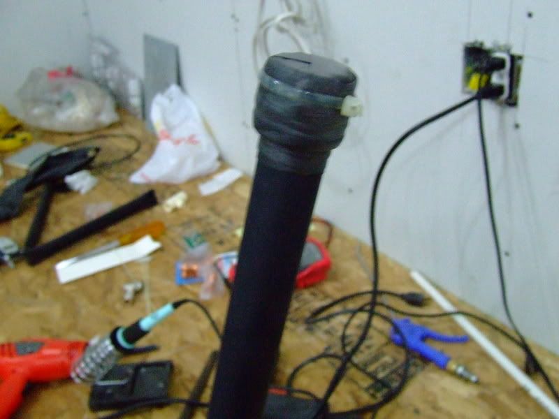
Step 12. Done, looks pretty sweet. Its about 5 feet tall, gonna mount in on the garage
DSCF4417.jpg


Reception was awesome. Worked REALLY well on VHF-AIR. usually with the rubber ducky i can hear the ATC, but not the pilot, and now i can hear the pilot and ATC the same. Last one was 80 miles away, 28000 Ft.

Also worked Extremely well on UHF around 300Mhz, 65Mhz as well.

Enjoy.
 

DaveH

Member
Joined
Jul 29, 2001
Messages
3,287
Location
Ottawa, Ont.
Great pictures and description of construction technique...although
many pix didn't make it through (including the final result). Did you
consider capping the ends (copper caps); and any concerns with
dissimilar metal contact i.e. corrosion?
Dave
 

NAVCAN

Member
Joined
Jul 30, 2006
Messages
34
Some pics didn't make it through? I see them all on my PC. Weird.

I did use PVC end caps on the tubes. And then taped them up.

DSCF4417.jpg


That's the final result. Just sideways.
 

KD8CPI

Member
Joined
Apr 24, 2006
Messages
44
Location
NW Ohio
I like how you did the Coax through the tubing. I made one similar and it was not to bad. I have also used it for local 2m transmit. using an HT.

Nice Job... Makes me want to redo mine.
 

kc9neq

Member
Premium Subscriber
Joined
Nov 15, 2006
Messages
226
Location
Illinois
looks great. i would like to make one for the railroad range 160 to 161 mhz range. where did you get the dimensions in order to make the antenna to the specific freq range?
 

Mark42

Member
Joined
Jan 31, 2007
Messages
23
Looks nice. I don't need another hobby... but...

What would happen if I soldered the coax (conductor & shield) directly
to the copper tubing instead of using the 75Ω/300Ω adapter?

I would leave the end cap off of the lower end, or put a hole for drainage
so the pipe doesn't fill with water (water always gets in everything eventually) :(

But I don't have time...

I'll take pictures when I don't do it. :D
 

jonny290

Member
Joined
Nov 15, 2006
Messages
687
Location
Denver, CO
You could improve the performance of this significantly by switching to the 'other' style of balun (the 1" by 3/8" long cylinder with a male F at one end, and a pair of spade wires on the other), and removing those 2 to 3 inch long wires. Those, twisted and coiled up as they currently are, present a varying inductance to the incoming RF, and very well may be killing the higher frequency potential of the antenna.

It just hurts to see stuff like N connectors..and then stuff like those patch wires. :p

Still, excellent construction, a nice piece of I do say so.
 

NAVCAN

Member
Joined
Jul 30, 2006
Messages
34
lol. I get the N connectors at work, they were in a toolbox that hadn't been opened in like 20 yrs, so I took them.

And refering to the wires, i cut about half the length off them before i taped the joint up, so the wires are only about 1.25 inches long.

So far, I've found extremely good reception from 40ish MHz to over 400Mhz, we don't have many 800 MHz systems in my town, if any, so Im stuck in the 150 range. And Mil-Air reception is absolutely AWESOME. TV brodcast was as clear as I've seen it with any of my homebrew antenna's.

Cheers. Thanks for the comments, I really like fabricating stuff.

And if your wondering, the copper tubes are covered in 1 inch heat shrink. Instead of paint.
 

jonny290

Member
Joined
Nov 15, 2006
Messages
687
Location
Denver, CO
I kind of was wondering - thought maybe you went nuts with a sixpack of electrical tape :D

Good going on the wire snips. Keep those connecting leads as short and low-impedance as possible - OCFD's need all the help they can get on higher frequencies, but they excel at their fundamental (design) frequency.
 

gcgrotz

Member
Joined
Feb 21, 2006
Messages
2,092
Location
Savannah, GA
I might have tried copper straps soldered to the pipe and then connected to the balun screws instead of the wire. Its a great looking antenna though and gave me lots of good ideas.

For Mark42: the balun is necessary for an OCF dipole because the impedance at that point is around 200 ohms. That is also what gives it good matching at even frequency multiples. The pipe construction at VHF/UHF gives it good bandwidth due to the relatively large diameter of the conductor relative to length.

I'm using one for HF cut for 7 MHz with low SWR, on 14 MHz it is below 2:1 over most of the ham band, and at 28.300 MHz it is around 1.9:1.
 

Mark42

Member
Joined
Jan 31, 2007
Messages
23
Thanks.

Is there really a reason to paint the copper?
They run copper pipe underground and air exposed w/o it corroding through...
the olive-drab patina of surface corrosion works as a protective coating.

I'll probably sand mine with 320 grit and clearcoat it just for looks. 8)

The plastic does need UV protection.

I was thinking of using one of the barrel shaped Balun adapters simply
so that I could hide it inside the horizontal pipe.

But first I'll make a simple wire OCD antenna just so I can quit using the stock rubber ducky.
 

NAVCAN

Member
Joined
Jul 30, 2006
Messages
34
That's not paint you see on the antenna. It's 1 1/8 inch heat shrink. And a whole lot of electrical super 88 tape, and stretch tape.
 

NAVCAN

Member
Joined
Jul 30, 2006
Messages
34
Ahoy, update.

Using a Bird AT-400 SWR meter, i obtained the following results:

65 Mhz - 1.4 : 1
100 Mhz - 3.1 : 1
150 Mhz - 2.0 : 1
200 Mhz - 1.6 : 1
250 Mhz - 1.6 : 1
300 Mhz - 2.4 : 1
350 Mhz - 2.5 : 1
400 Mhz - 2.5 : 1
420 Mhz - 1.9 : 1
430 Mhz - 1.7 : 1
440 Mhz - 1.5 : 1
450 Mhz - 1.14 : 1
520 Mhz - 1.14 : 1

That's the maximum frequency the Bird allows you to test. I'm pretty fraggin happy.
 
N

N_Jay

Guest
NAVCAN said:
Ahoy, update.

Using a Bird AT-400 SWR meter, i obtained the following results:

65 Mhz - 1.4 : 1
100 Mhz - 3.1 : 1
150 Mhz - 2.0 : 1
200 Mhz - 1.6 : 1
250 Mhz - 1.6 : 1
300 Mhz - 2.4 : 1
350 Mhz - 2.5 : 1
400 Mhz - 2.5 : 1
420 Mhz - 1.9 : 1
430 Mhz - 1.7 : 1
440 Mhz - 1.5 : 1
450 Mhz - 1.14 : 1
520 Mhz - 1.14 : 1

That's the maximum frequency the Bird allows you to test. I'm pretty fraggin happy.

SWR is not necessarily a good indication of antenna efficiency.
 

NAVCAN

Member
Joined
Jul 30, 2006
Messages
34
I know, I was just testing the SWR.

The Bird Antenna tester can also check antenna efficiency.

I'll let you know.
 

briano

Member
Joined
Jul 19, 2006
Messages
64
I would like to see the results. I build one of these with 1" copper.
I have only used it indoor so far. Need to make it weatherproof before it goes outside. My very first impression is that it is good at picking up interference from my computer that is 8ft. away.
 

briano

Member
Joined
Jul 19, 2006
Messages
64
NAVCAN

What is the going rate for a Bird AT-400?

Any efficiency results yet?
 

NAVCAN

Member
Joined
Jul 30, 2006
Messages
34
The going rate of the bird 400 is free for me, I just borrowed it from work.

And sorry for the delayed reply, i've been really busy painting cars on the side lately. hardly any time to visit the forum anymore. I'll get those eficiency numbers soon.

Cheers.
 
Status
Not open for further replies.
Top