• To anyone looking to acquire commercial radio programming software:

    Please do not make requests for copies of radio programming software which is sold (or was sold) by the manufacturer for any monetary value. All requests will be deleted and a forum infraction issued. Making a request such as this is attempting to engage in software piracy and this forum cannot be involved or associated with this activity. The same goes for any private transaction via Private Message. Even if you attempt to engage in this activity in PM's we will still enforce the forum rules. Your PM's are not private and the administration has the right to read them if there's a hint to criminal activity.

    If you are having trouble legally obtaining software please state so. We do not want any hurt feelings when your vague post is mistaken for a free request. It is YOUR responsibility to properly word your request.

    To obtain Motorola software see the Sticky in the Motorola forum.

    The various other vendors often permit their dealers to sell the software online (i.e., Kenwood). Please use Google or some other search engine to find a dealer that sells the software. Typically each series or individual radio requires its own software package. Often the Kenwood software is less than $100 so don't be a cheapskate; just purchase it.

    For M/A Com/Harris/GE, etc: there are two software packages that program all current and past radios. One package is for conventional programming and the other for trunked programming. The trunked package is in upwards of $2,500. The conventional package is more reasonable though is still several hundred dollars. The benefit is you do not need multiple versions for each radio (unlike Motorola).

    This is a large and very visible forum. We cannot jeopardize the ability to provide the RadioReference services by allowing this activity to occur. Please respect this.

Hy Gain Big Gun 2

Status
Not open for further replies.

FPR1981

Active Member
Joined
Feb 1, 2021
Messages
621
I remember seeing a set of these monsters on a house across from the radio station I used to work for. They looked like a Moonraker 4 on steroids. Absolutely giant.

Imagine my shock and surprise when I found some vintage advertising that showed this antenna's power handling to be only 1kw P.E.P. I realize that is a lot of output power, but I've seen some omnidirectional antennas rated at 3kw P.E.P.

Wonder why only 1kw of handling power with these. What would burn up if you put more through them?
 

FPR1981

Active Member
Joined
Feb 1, 2021
Messages
621
Oops, revised illustration. wrong one before.
 

Attachments

  • cb_mag_oct_1974_pg31.png
    cb_mag_oct_1974_pg31.png
    348.8 KB · Views: 27

FPR1981

Active Member
Joined
Feb 1, 2021
Messages
621
The Astrobeam had a phasing harness that calls for two lengths of RG59 to get the impedance down to 35 ohms and I have heard a similar tale about it not being able to take a lot of power
 

JayMojave

Member
Joined
Dec 13, 2007
Messages
722
Location
Mojave Ca
Yeah RG11 is also 75 ohm coax that will take more power Iam sure. One would need to find the insulation voltage break down spec if there is one. The CB Quad Beam Antennas used cheap 14 gauge magnet wire for the quad loops so that the manufactures cold save money. I have rebuit a few PDLII and Moonraker antennas, I use 10 gauge Thermaleze coated wire not so much to take more power, but it doesn't stretch over time and change the antennas operating frequency. Even the assembly instructions for these antennas tell you to pre-stretch the 14 gauge wire.

See: Wire, Tape, PTFE Tubing (amidoncorp.com)

A torrid type impedance matching Balun could be used for matching allowing more steam to the antenna.

Jay in the Great Mojave Desert
 

FPR1981

Active Member
Joined
Feb 1, 2021
Messages
621
I see RG83 is commercially available and is already 35 ohms. I suppose it could be used for the phasing harness on the Astrobeam, but I would be curious how much output power it could handle.
 

KB4MSZ

Billy
Premium Subscriber
Joined
Mar 12, 2018
Messages
1,017
Location
Tampa, Florida
The higher impedance cable can sustain more voltage and has less signal loss, but looses power handling, and peaks at about 75 ohms. Lower impedance can handle more power, but has more signal loss and breaks down with voltage faster, this peaks down at about 30 ohms. This was research done by Bell Lab engineers Espenscheid and Eiffel back at the end of the 20's. The compromise was reached with the 50 ohm value.
 

prcguy

Member
Joined
Jun 30, 2006
Messages
17,569
Location
So Cal - Richardson, TX - Tewksbury, MA
M2 uses RG-6 cable in their Yagi T-match baluns that are rated at 1500 watts. You could use 75 ohm RG-11 which will handle a lot of power. The RG-59 used in the 1970s was solid polyethylene dielectric and modern RG-6 and RG-11 uses lower loss foam, which will have a different velocity factor. If replacing an old phasing harness with new coax you would have to calculate a different length.
 

FPR1981

Active Member
Joined
Feb 1, 2021
Messages
621
M2 uses RG-6 cable in their Yagi T-match baluns that are rated at 1500 watts. You could use 75 ohm RG-11 which will handle a lot of power. The RG-59 used in the 1970s was solid polyethylene dielectric and modern RG-6 and RG-11 uses lower loss foam, which will have a different velocity factor. If replacing an old phasing harness with new coax you would have to calculate a different length.

My research is telling me that some AstroBeams came with twin RG59U 75-ohm cables at 6' long, wired in parallel, for an outcome of 35 ohms.

Some other astrobeams came with a single length of RG83U, at 6' long, and this cable was 35 ohms to begin with.

So, with RG11, would I use the twin 6' scheme?
 

prcguy

Member
Joined
Jun 30, 2006
Messages
17,569
Location
So Cal - Richardson, TX - Tewksbury, MA
If its simply the antenna having a 35 ohm impedance at the feedpoint there are other ways of matching it like a broad band transformer or a hairpin loop. When you take an antenna that is close to 50 ohms like an omni Astroplane, then stuff it close in to a reflector and a director, it pulls the impedance way down. Most Yagi antennas have a gamma match or a T match or if its an insulated dipole, a hairpin loop is perfect way to raise its impedance closer to 50 ohms. I would dump the coax matching section and use a more modern approach.

In fact I did this with a couple of very rare Shakespeare Yagis. Within a months time a 3 element and then a 4 element Shakespeare all fiberglass Yagi came up on Ebay and I got them both for nearly nothing, like $40 each and from different sellers and new in box! Before that I had never seen one in person in my life. They had a goofy parallel coax harness thing probably similar to the Astro beam that needed to be grounded to a mast and I replace that with a hairpin match and ferrite choke balun. The antenna's finally had a great match that was consistent no matter what you mounted them to. I cut one down to 10m amateur and it worked so well I cut the other one down. I now regret that as it would have been the most perfect portable CB Yagi ever. You just screw in a bunch of fiberglass whips and go.

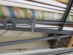
Here is a picture of the hairpin loop and balun, painted over with gray paint in the rafters of my garage.

Hairpin match.JPG

My research is telling me that some AstroBeams came with twin RG59U 75-ohm cables at 6' long, wired in parallel, for an outcome of 35 ohms.

Some other astrobeams came with a single length of RG83U, at 6' long, and this cable was 35 ohms to begin with.

So, with RG11, would I use the twin 6' scheme?
 

FPR1981

Active Member
Joined
Feb 1, 2021
Messages
621
Beam antennas are a new area of study for me. If you knew of a solution to this matching harness issue, I'd either pay you a consult fee or if you could design it and make it, I would buy it from you.
 

prcguy

Member
Joined
Jun 30, 2006
Messages
17,569
Location
So Cal - Richardson, TX - Tewksbury, MA
However the RG-59 was used, RG-11 would be the same except for a slight change in length due to different velocity factors. Since there were two parallel lengths of RG-59, the power handling would be about twice what a single run of RG-59 would take and I would guess the parallel run should handle at least 500 watts intermittently.

My research is telling me that some AstroBeams came with twin RG59U 75-ohm cables at 6' long, wired in parallel, for an outcome of 35 ohms.

Some other astrobeams came with a single length of RG83U, at 6' long, and this cable was 35 ohms to begin with.

So, with RG11, would I use the twin 6' scheme?
 
Last edited:

prcguy

Member
Joined
Jun 30, 2006
Messages
17,569
Location
So Cal - Richardson, TX - Tewksbury, MA
I would want to put an antenna analyzer right at the feedpoint and measure the impedance. Is it right at 35 ohms or is it 40 ohms or 25 ohms? A 1:2 balun that matches 50 to 25 ohms might work fine. Here are instructions on how to make one and there are several other ways.


Beam antennas are a new area of study for me. If you knew of a solution to this matching harness issue, I'd either pay you a consult fee or if you could design it and make it, I would buy it from you.
 

JayMojave

Member
Joined
Dec 13, 2007
Messages
722
Location
Mojave Ca
And again... what PRCGUY said!

Don't understand the RG83 a 35 Ohm Coax being used, as the RG59 a 75 Ohm Coax cut to a 1/2 wave length will transform 50 Ohm impedance to 25 / 35 Ohms to get you close to a good match.

PRCGUY photo shows a impedance matching Balun and a "Hairpin" matching stub, first used in CB Beam Antennas by Hy-Gain that had a outside HF Antenna Range with real world Electromagnetic Engineers and antenna measuring equipment. Allowing a "Big Strap" to adjust his beam to dead nuts VSWR. Good stuff. Watching the VSWR while dropping the hammer with said high steam levels allows one to monitor the antenna/amp functions if any thing goes wrong should the VSWR increase.

But present manufactures use a Gamma Match to save money at time in their manufacturing process. I am not impressed with the Gamma Match.
I use the gamma match to stir paint.

Jay in the Great Mojave Desert.... "Next Gas 150 Miles"
 

prcguy

Member
Joined
Jun 30, 2006
Messages
17,569
Location
So Cal - Richardson, TX - Tewksbury, MA
A half wavelength in coax adjusted with velocity factor will "see" the same impedance repeated at the end of that half wavelength coax similar to measuring the VSWR where the coax is connected. A half wavelength of 75 ohm coax is used in a phasing harness to make a power divider and that's different because there are two lengths connecting two 50 ohm things to one common 50 ohm point. I believe a different length of odd impedance coax would be used for impedance matching of a single coax run like feeding a 35 ohm driven element.

Don't understand the RG83 a 35 Ohm Coax being used, as the RG59 a 75 Ohm Coax cut to a 1/2 wave length will transform 50 Ohm impedance to 25 / 35 Ohms to get you close to a good match.

Jay in the Great Mojave Desert.... "Next Gas 150 Miles"
 

JayMojave

Member
Joined
Dec 13, 2007
Messages
722
Location
Mojave Ca
Hello ALL: Thanks PRCGUY greatly appreciated for the learning there, I didn't know the 1/2 wave length coax could also match the impedance. Thanks again. Makes sense now.

Jay in the Great Mojave Desert.... "Next Gas 150 Miles"
 

prcguy

Member
Joined
Jun 30, 2006
Messages
17,569
Location
So Cal - Richardson, TX - Tewksbury, MA
The same holds true for using a Bird or any other wattmeter to get a more precise reading when the load is not a perfect 50 ohm resistive. This is from the Bird 43 operating manual:

"When a Bird 43 is used to tune a load to a transmitter and a good match is obtained, removing the unit will not change the match quality. A good 50 ohm load can terminate a 50 ohm transmission line of any length without altering conditions at the transmitter. The 43 is just an extra length of 50 ohm line in series with the measurement. When the load is not well matched (an antenna with a VSWR of 1.5 or 2.0) the line length between the load and the transmitter will transform the load impedance as seen at the transmitter. Removing the wattmeter shortens the total line length by four inches plus two connectors. This is still not significant at low frequencies where five inches is a small fraction of a wavelength, but at higher frequencies the frequency or power output of the transmitter may be affected. Transmission line theory shows that if the line length changes by exactly 1/2 wavelength, the impedance is unchanged. To have identical match with the wattmeter in or out of the circuit, insert or remove 1/2 wavelength of line (including the unit). To do this, use a length of cable which, when added to the unit, equals a 1/2 wavelength at the frequency of interest. If multiple frequencies are needed, a separate cable length is required for each. See Figure 10 for sample cable lengths."

Hello ALL: Thanks PRCGUY greatly appreciated for the learning there, I didn't know the 1/2 wave length coax could also match the impedance. Thanks again. Makes sense now.

Jay in the Great Mojave Desert.... "Next Gas 150 Miles"
 
Status
Not open for further replies.
Top