Makita tough radio mod

Status
Not open for further replies.

OK2BCK

Member
Joined
Aug 12, 2008
Messages
90
Location
New Zealand, Napier
Hi there,
I have recently got this great Makita radio (just a broadcast receiver FM + MW) which many other chaps I meet at work every day, have been using for a while now. The only thing I found a little limitting was the need of use (almost any) Makita powertool battery or silly little power pack to make this cute little beast to sing. Soon I have realised that it was actually designed to be modified to it's perfection, going through few simple steps. These are: cutting off the battery holder at the back of the unit and installing 12V/7Ah sealed lead-acid battery, small charger, transformer, power cable outlet and a battery switch.

The radio itself has outstanding sound and surprisingly powerful output!
There are two AUX inputs for external audio sources, sleep timer, alarm clock and slot for two AA batteries, in order to keep the clock when the main battery is not fitted (in this case, when the main battery is switched off)

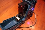
Radio before modification:
opened small.jpg

Modifications;
-battery switch on front panel (red led toggle switch)
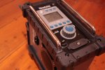
battery switch.JPG


-mains power connector (the lcd is blue, so blue led as a mains indicator)
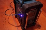
charging.JPG


-big battery and transformer
battery.JPG


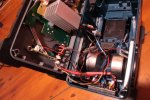
-just add wires
guts1.JPG


Now it is what I call good portable stereo/amp for any occasion!
more photos here

My apology for bad quality photos due to bad light and me being lazy.
I can shoot some more if you ask ;)

Makita
 

OK2BCK

Member
Joined
Aug 12, 2008
Messages
90
Location
New Zealand, Napier
Thanks,
The charger unit is recycled from old phone system backup power unit.
There is six terminals: 16VAC from transformer, battery pos/neg and continuous 12V output. Two LED lights indicating presence of AC and battery (which I extended and used as well).

These little charger units designed to charge sealed 7Ah lead-acid batteries are used in security industry as most of detectors and locks use 12VDC.
In my opinion, Canadian PARADOX makes the cutest modules ever. And cheap.

If you find any kind of old equipment containing these sealed batteries, there is very big chance to find some kind of power supply / charger module inside as well. And because I am such a junk collector...
 

tintin20_2

Newbie
Joined
Jan 18, 2011
Messages
1
hi, really like the idea and project and would like to try this for myself, could u please give more information about the extra wiring, installation also ratings of the transformer?

just wondered if there was any reason you used a 16v transformer?

have electrical experience myself ,but must admit thought this was a very clever and well thought out idea,

the extra explanations would help alot.

well done!!
 

OK2BCK

Member
Joined
Aug 12, 2008
Messages
90
Location
New Zealand, Napier
hi, really like the idea and project and would like to try this for myself, could u please give more information about the extra wiring, installation also ratings of the transformer?

just wondered if there was any reason you used a 16v transformer?

have electrical experience myself ,but must admit thought this was a very clever and well thought out idea,

the extra explanations would help alot.

well done!!

hey could you email me the build on how you did it???? or like messege me thanks

Just found my old post here by accident. I've suffered hdd failure that time - if you guys still interested in more info please let me know.

My apologies
 

ChrisK7

Newbie
Joined
May 20, 2012
Messages
2
Location
Vancouver, Canada
Hi Jan

I'm also interested in how you accomplished this mod. I install security systems for a living, so I have experience with low voltage wiring, but I'm hoping you can give me a shove in the right direction so I could try this for myself?

Thank you,
Chris
 

OK2BCK

Member
Joined
Aug 12, 2008
Messages
90
Location
New Zealand, Napier
Hi Jan

I'm also interested in how you accomplished this mod. I install security systems for a living, so I have experience with low voltage wiring, but I'm hoping you can give me a shove in the right direction so I could try this for myself?

Thank you,
Chris


Hello Chris, nice to hear from you.
This mod includes wiring of a mains plug in the radio, make sure that you know what you doing!


So later after I posted this I have changed the transformer to slightly bigger and to paradox charger board. They are sold together as a kit.

The radio originally has a battery dock that I have cut out with hack saw blade. (keep in mind two battery contact wires are the main power input for the radio)

The 7Ah battery is a tight fit and luckily, the back "firewall" can just stay there! That was the luckiest bit, the whole reason I did this.
The safer way would be to keep the transformer on the main body part, but there is a battery backup bay (2xAA) right on the bottom of the "firewall". You can see how high the battery has to hold there for that reason, I used some rack-mount bracket of some old equipment and some beefy cable ties to keep it in place. The bracket should be bolted down using nylock nuts and the biggest washers available.

The front 'charger' inlet harness was removed and the rubber cap was glued down. Perhaps can be fitted with second AUX IN that is at the battery bay!

I have drilled through the front panel close to volume knob to fit a battery switch. (please use decent switch ideally with an LED)

The mains power socket is from old computer power supply and has to be wired correctly. I haven't use a mains switch because I wanted the radio to simply charge when it's plugged in. If your socket does not have fuse inside, use insulated panel fuse holder.

The charger board has AC input from the transformer, 12V battery input and 12VDC output with backup.
There is also a LED that is coupled to the current draw to the battery, when the battery is being charged the LED is ON. I have unsoldered the LED and replaced it with bright blue LED that lives next to the mains connector.
The charger board itself is attached to the bottom floor in between the speakers. I use 3M 6382 foam tape if I want something to stay there

Wiring?
I have connected the radio to 12VDC output, battery runs through a switch on front panel. The LED on that switch has 470ohm resistor on one of it's legs, all connected to the battery terminal on the board.
If you connect the radio to the battery input on the board, you get it to run longer but the cut-out will be down to 9V which is not healthy for the battery.
If you do use the same board, remove the jumper for higher charging current. It should be also possible to tweak the charging voltage threshold up to 14 volts or so (better for cyclic use) but I have never even tried.
Also, let's say all wiring should be cable tied to something solid, LED wiring harness should be glued down. That and good cable ties (with through-holes drilled with a strategy) to hold the battery and your mod should survive daily use.
 
Last edited:

ChrisK7

Newbie
Joined
May 20, 2012
Messages
2
Location
Vancouver, Canada
THANK YOU! That's definitely the push in the right direction I was looking for and more. Once I've attempted my mod I'll post the results and some pics.

Again, I really appreciate your help.

Chris
 
Status
Not open for further replies.
Top