
Multi-use Driver Assembly
I enjoy experimenting, and soon grew tired of building complete new antennas for each band I wanted to snoop around in. After trying different methods of construction I came up with a method that seems to work really well for low VHF and up. I guess it could also be applied to the higher HF bands but that wouldn’t be for the faint of heart.
The design centers around an assembly of “driver elements”, each of which are identical and each with its own feed point. Since each driver element is identical, only the first driver requires sizing up of the internal conductor lengths for assembly. After the lengths have been established, the internal conductors can be cut and bent in the quantity required for the number of drivers for a given project. Shown below is an example of a fully assembled driver.

The driver body is PVC pipe

Overall of one side of the driver assembly

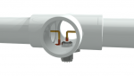
Transparency of one side of the driver assembly

Fully assembled driver array

Close up of tuning tip and feed point

Close up of tuning tip Note: the PVC pipe is shown capped, I later found using a coupling and plug
to be better for mounting the SO-239 as the plug has a flat surface. For SO-239 use, the PVC 1” ID provides a good fit.
The tuning tip (and the internal element conductor) is 3/32” brass brazing rod. This rod size slides into the center conductor of the PL-259, and is soldered at the plug tip as well as at the brass washer and the PL-259 reducer contact points. I solder the reducer, washer and rod to ensure that no capacitive effect is created between the rod and the body of the PL-259 which might produce an intermittent reaction when installed and in use. In the case of a transmitting antenna, this area is going to be at near the highest voltages and any reactive component in this area could be a problem.
The length chosen for the PVC drivers would be determined by the range of operating frequencies desired, and based on brass rod length availability (in this case 36”). My current driver elements are 40” long, 20” each side of the feed point. This length is not super critical, as the final element length is controlled and tuned by removing the PL-259 connection and trimming the extending rod to length. By having the tips removable it is easy to trim each set exactly uniform, due to the fact that the rods can be stood together and trimmed. In the case of accidental over trimming, unsolder the old rod and solder a new on in its place.
The antenna shown in this example is a five element beam, with three elements driven or “active”. The front and back elements are a non-driven director and reflector. The three driven elements are designed to have the center driven element at the center of the band, in this case the six meter band and tuned for 52 MHz. The other two driven elements are treated as parasitic, the front driven element is 4.5% higher in frequency, the rear driven element 4.5% lower. The non-active director and reflector are 4.5% offset in frequency from the front and rear driven elements, respectively.

Inactive “driver” element
The inactive “drivers” are fully constructed just as the active drivers are, but the PL-259 is internally shorted and attached to provide a continuous element. This is done to keep the dimensional aspect of the passive elements the same at their feed point as the active drivers. This insures that the design frequency of the passive elements will be maintained.

Overall top view of the five element beam assembly
Because each element is capable of being either driven or passive by using a shorted PL-259 plug, the elements can be reused and arranged in most any combination of number of driven elements or passive elements. Changing to entirely different frequency bands is easily achieved by changing the brass rod tips, and cutting new length PVC spacers to insert between the element assemblies for spacing. The driven elements are fed first at the front (highest frequency) driver, and successively interconnected with T fittings and, at the rear driver, a 90 degree elbow fitting. The active elements can be rotated 180 degrees with respect to each other, to alternate the phase of the signal through the path of the element array. This is done by spinning every other element 180 degrees in plan view, as in the rendering above.
Below are renderings of closer details of the tip and feed point assemblies. Note that the ends are capped, I ended up using a coupling and plug fitting instead for better mounting of the SO-239 fitting.

Driver end detail

Driver end detail transparency. The brass rod is soldered to the SO-239 fitting once the rod length has
been determined and then slid into the tube and soldered at the feed point
I enjoy experimenting, and soon grew tired of building complete new antennas for each band I wanted to snoop around in. After trying different methods of construction I came up with a method that seems to work really well for low VHF and up. I guess it could also be applied to the higher HF bands but that wouldn’t be for the faint of heart.
The design centers around an assembly of “driver elements”, each of which are identical and each with its own feed point. Since each driver element is identical, only the first driver requires sizing up of the internal conductor lengths for assembly. After the lengths have been established, the internal conductors can be cut and bent in the quantity required for the number of drivers for a given project. Shown below is an example of a fully assembled driver.
The driver body is PVC pipe
Overall of one side of the driver assembly
Transparency of one side of the driver assembly
Fully assembled driver array
Close up of tuning tip and feed point
Close up of tuning tip Note: the PVC pipe is shown capped, I later found using a coupling and plug
to be better for mounting the SO-239 as the plug has a flat surface. For SO-239 use, the PVC 1” ID provides a good fit.
The tuning tip (and the internal element conductor) is 3/32” brass brazing rod. This rod size slides into the center conductor of the PL-259, and is soldered at the plug tip as well as at the brass washer and the PL-259 reducer contact points. I solder the reducer, washer and rod to ensure that no capacitive effect is created between the rod and the body of the PL-259 which might produce an intermittent reaction when installed and in use. In the case of a transmitting antenna, this area is going to be at near the highest voltages and any reactive component in this area could be a problem.
The length chosen for the PVC drivers would be determined by the range of operating frequencies desired, and based on brass rod length availability (in this case 36”). My current driver elements are 40” long, 20” each side of the feed point. This length is not super critical, as the final element length is controlled and tuned by removing the PL-259 connection and trimming the extending rod to length. By having the tips removable it is easy to trim each set exactly uniform, due to the fact that the rods can be stood together and trimmed. In the case of accidental over trimming, unsolder the old rod and solder a new on in its place.
The antenna shown in this example is a five element beam, with three elements driven or “active”. The front and back elements are a non-driven director and reflector. The three driven elements are designed to have the center driven element at the center of the band, in this case the six meter band and tuned for 52 MHz. The other two driven elements are treated as parasitic, the front driven element is 4.5% higher in frequency, the rear driven element 4.5% lower. The non-active director and reflector are 4.5% offset in frequency from the front and rear driven elements, respectively.
Inactive “driver” element
The inactive “drivers” are fully constructed just as the active drivers are, but the PL-259 is internally shorted and attached to provide a continuous element. This is done to keep the dimensional aspect of the passive elements the same at their feed point as the active drivers. This insures that the design frequency of the passive elements will be maintained.
Overall top view of the five element beam assembly
Because each element is capable of being either driven or passive by using a shorted PL-259 plug, the elements can be reused and arranged in most any combination of number of driven elements or passive elements. Changing to entirely different frequency bands is easily achieved by changing the brass rod tips, and cutting new length PVC spacers to insert between the element assemblies for spacing. The driven elements are fed first at the front (highest frequency) driver, and successively interconnected with T fittings and, at the rear driver, a 90 degree elbow fitting. The active elements can be rotated 180 degrees with respect to each other, to alternate the phase of the signal through the path of the element array. This is done by spinning every other element 180 degrees in plan view, as in the rendering above.
Below are renderings of closer details of the tip and feed point assemblies. Note that the ends are capped, I ended up using a coupling and plug fitting instead for better mounting of the SO-239 fitting.
Driver end detail
Driver end detail transparency. The brass rod is soldered to the SO-239 fitting once the rod length has
been determined and then slid into the tube and soldered at the feed point


")