• To anyone looking to acquire commercial radio programming software:

    Please do not make requests for copies of radio programming software which is sold (or was sold) by the manufacturer for any monetary value. All requests will be deleted and a forum infraction issued. Making a request such as this is attempting to engage in software piracy and this forum cannot be involved or associated with this activity. The same goes for any private transaction via Private Message. Even if you attempt to engage in this activity in PM's we will still enforce the forum rules. Your PM's are not private and the administration has the right to read them if there's a hint to criminal activity.

    If you are having trouble legally obtaining software please state so. We do not want any hurt feelings when your vague post is mistaken for a free request. It is YOUR responsibility to properly word your request.

    To obtain Motorola software see the Sticky in the Motorola forum.

    The various other vendors often permit their dealers to sell the software online (i.e., Kenwood). Please use Google or some other search engine to find a dealer that sells the software. Typically each series or individual radio requires its own software package. Often the Kenwood software is less than $100 so don't be a cheapskate; just purchase it.

    For M/A Com/Harris/GE, etc: there are two software packages that program all current and past radios. One package is for conventional programming and the other for trunked programming. The trunked package is in upwards of $2,500. The conventional package is more reasonable though is still several hundred dollars. The benefit is you do not need multiple versions for each radio (unlike Motorola).

    This is a large and very visible forum. We cannot jeopardize the ability to provide the RadioReference services by allowing this activity to occur. Please respect this.

Specific interference on the VHF Business High band

videobruce

Member
Premium Subscriber
Joined
Jan 5, 2004
Messages
403
Location
Buffalo NY
Yes to what? Raises or lowers the impedance? Actually, is it changing the frequency and which way?

(Smith charts I don't even begin to understand, besides it's way beyond my pay grade.)
 

prcguy

Member
Joined
Jun 30, 2006
Messages
15,385
Location
So Cal - Richardson, TX - Tewksbury, MA
Yes to what? Raises or lowers the impedance? Actually, is it changing the frequency and which way?

(Smith charts I don't even begin to understand, besides it's way beyond my pay grade.)
Changing the size of the U changes impedance within its useable range. You can make it too big or small and that may affect the resonant freq. I don’t know if making it bigger raises or lowers the impedance.
 

videobruce

Member
Premium Subscriber
Joined
Jan 5, 2004
Messages
403
Location
Buffalo NY
I was referring to it's length, leaving the width at 1" per the original design for 146 MHz. The gap between the two driven element halfs is 1". Doesn't that fix the width of the 'U' leaving the only adjustment choice length??
 

videobruce

Member
Premium Subscriber
Joined
Jan 5, 2004
Messages
403
Location
Buffalo NY
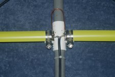
It was asked if I noticed changes in the pattern of the interference with any weather changes. Up to a couple of weeks or so ago, there wasn't since there weren't any real changes in the weather,
but,
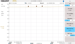
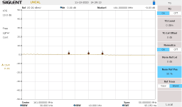
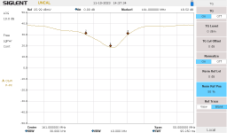
from last weekend to now the interference has completely stopped, or at least drifted outside of the frequency area of interest. Nothing as far as I can tell. The temperature has dropped 20+ degrees overall 4 or 5 days ago and we have had some, but not much rain. Before, we were in a dry spell and in the upper 80's during the day. Now it's mid fifties and mid 40's at night.

That can't just be coincidence. Any thoughts on this??
 

videobruce

Member
Premium Subscriber
Joined
Jan 5, 2004
Messages
403
Location
Buffalo NY
Attached are scans of the corrected yagi with shortened leads from the feed, a trimmed director length (less than 1/4" was trimmed off and remounted driven elements (my 1st cut was 1/2" which was too much, I cut two new pieces). I also spaced those further apart on the 'cross' fitting per the original design (see pics).

I tested on a rear porch securing to to a wooden railing, later having my XYL hold the antenna in different positions away from the porch roof as much as possible while I watched the SA to see if the notch varied.

This behaved differently as to the level settings that I'm use to using. I included scans w/o a load (after normalizing w/ a load), another scan with the load, and two scans w/ the antenna attached (via a 15-18' RG-58 cable), the last pic was w/ the marker table showing.
 

Attachments

  • 161MHz yagi feed point.JPG
    161MHz yagi feed point.JPG
    117.9 KB · Views: 9
  • Yagi scan with open RLB port.png
    Yagi scan with open RLB port.png
    13.5 KB · Views: 8
  • Yagi scan w 50 ohm load.png
    Yagi scan w 50 ohm load.png
    13.5 KB · Views: 8
  • Yagi sweep back porch.png
    Yagi sweep back porch.png
    14.4 KB · Views: 7
  • Yagi scan back porch w table.png
    Yagi scan back porch w table.png
    15.9 KB · Views: 8

Ubbe

Member
Joined
Sep 8, 2006
Messages
9,055
Location
Stockholm, Sweden
I would regard that dip to be the S11 value and any single band antenna I have measured are around that same 20dB value indicating that the antenna has a low SWR. If it's only a 15dB drop or less then something isn't right.

If you cut elements too short then just move them out so that their tips have the correct distance. It doesn't matter much if there's a bigger gap in the middle, especially if you splice the coax a bit more that will then replace the missing elements.

/Ubbe
 

videobruce

Member
Premium Subscriber
Joined
Jan 5, 2004
Messages
403
Location
Buffalo NY
I showed those two scans, one with a 50 ohm load connected and the other with no load since the overall initial settings to bring the trace on screen was considerably different than most other TG scans I have done. I normally set the 'Norm Ref Pos' to 90%, here I had to reduce it to 50%
 
Top