
- Forums
- Scanners, Receivers and Related Equipment Forums
- Antennas and Associated Hardware
- Coax Cable and Connectors
You are using an out of date browser. It may not display this or other websites correctly.
You should upgrade or use an alternative browser.
You should upgrade or use an alternative browser.
What exactly does it mean to ground a Antenna?
- Status
- Not open for further replies.
KA9QPN
Member
The short version of NEC Article 810:
Installing radio and TV antenna systems | Code Basics content from Electrical Construction & Maintenance (EC&M) Magazine
Tom KA9QPN
Installing radio and TV antenna systems | Code Basics content from Electrical Construction & Maintenance (EC&M) Magazine
Tom KA9QPN
MichaelxB
Member
The short version of NEC Article 810:
Installing radio and TV antenna systems | Code Basics content from Electrical Construction & Maintenance (EC&M) Magazine
Tom KA9QPN
Thanks for this fellas.
MichaelxB
Member
There are a couple of reasons to ground your antennas. The first is that your home owners house insurance requires it. It would be best to ask them what their requirements are before you do much. They are the ones that will have to pay for any damages. If you don't do it to their specs, they really don't have to pay the claim.
Another reason is for personal safety. There can be a tremendous difference of voltage (potential) between metallic objects in your radio area and other electrical objects like outlets, appliances, air conditioner ducts and so on during a lightning strike. They all need to be bonded together with a common ground. this is why you keep hearing about making sure your tied to the same ground rod the electrical meter is tied to. Not to your breaker panel. The breaker panel is not the correct place to have the common ground.
The last reason is as others have said is the grounding section 250 of the NEC (national Electrical Code). It gives the guidelines on how grounding should be done at your house. The grounding rods and how connections should be made are spelled out. The grounding rods are steel with copper clad. You can find galvanized rods for special applications where electrolysis can be an issue.
One real important point to remember is that you don't want to drive multiple ground rods next to each other and then connect them all together. They need to be separated by twice their length. If yo use 8 foot ground rods, they should be 16 feet apart. This is due to the cone of influence around each ground rod. Spacing them closer will cause this cone to be intersected by the other ground rod. Doing this reduces the effective low resistance that each ground rod can contribute. If you have sandy soil, the ground rods will need to be longer and spaced further apart. It is not uncommon to have to use rods that may extend down to 20 or even 40 feet.
Grounding is a science and there are not that many people that really understand it. But you will find all sorts of know it all's that will provide information that is really lacking the truth behind it and engineering that good grounding requires. Make sure you know where the source of information you receiving is good. If your unsure, the Internet is your best friend. But you might have to do some hard searching to get the answer you should be getting.
Thanks for the explanation Jim
fleef
Kristin Cavazos Phoenix Arizona
This person wanted a video practically
So they are really new- lots of technical info in those replies hee hee
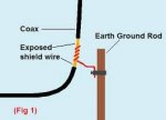
Say OP what you can do is- say if you have a coax (those thick cables you use for cable TV? ) if one of those is the "feed line" to your antenna, you want to scrape away the outer plastic coating JUST til you get to the metallic foil wrap "metallic shield" THIS PART: https://encrypted-tbn3.gstatic.com/..._M0fN6MTJjLpUzhQ8nL2dxKor4MrahBaCGPdve_O-lJy8
, that is the "shielding" you want to connect to ground. Take a ground clamp or solder wire to that do it as close to where it meets the antenna say outside on the lawn if your antenna is outside. There are several "grounds" you can use- in a pinch for indoors I have used an unused land line telephone jack wall plate, even an electric socket wall plate (both too noisy!!)
if you have copper cold water pipes (many dont these days) can use those.
OR
big ground stake in the ground.
Here is EXACTLY a picture of what I mean and the EASIEST - pay attention to the image url i inserted above, it shows you what part on coax to connect to your grounding wire etc. You just scrape off the outside coating of coax to get to the metallic sleeve it may be silver or copper colored but of course NOT the "stinger" which is the copper wire in the very center of coax because that is the part you connect to your antenna obviously
https://encrypted-tbn1.gstatic.com/...IFk3mgO7RuTaQFoHrKRfND15Con6yQW6EtVsrEMjiDHCZ
some people are telling you to ground for "Safety" reasons um pardon me but i do it for "antenna" reasons- a good source for more info may be "eham.net" lots of old timers and lots of grounding how to/forum discussion etc. Good luck use a ground or not- give radio a listen see if it helps! make sure you do it right first though
So they are really new- lots of technical info in those replies hee hee
Say OP what you can do is- say if you have a coax (those thick cables you use for cable TV? ) if one of those is the "feed line" to your antenna, you want to scrape away the outer plastic coating JUST til you get to the metallic foil wrap "metallic shield" THIS PART: https://encrypted-tbn3.gstatic.com/..._M0fN6MTJjLpUzhQ8nL2dxKor4MrahBaCGPdve_O-lJy8
, that is the "shielding" you want to connect to ground. Take a ground clamp or solder wire to that do it as close to where it meets the antenna say outside on the lawn if your antenna is outside. There are several "grounds" you can use- in a pinch for indoors I have used an unused land line telephone jack wall plate, even an electric socket wall plate (both too noisy!!)
if you have copper cold water pipes (many dont these days) can use those.
OR
big ground stake in the ground.
Here is EXACTLY a picture of what I mean and the EASIEST - pay attention to the image url i inserted above, it shows you what part on coax to connect to your grounding wire etc. You just scrape off the outside coating of coax to get to the metallic sleeve it may be silver or copper colored but of course NOT the "stinger" which is the copper wire in the very center of coax because that is the part you connect to your antenna obviously
https://encrypted-tbn1.gstatic.com/...IFk3mgO7RuTaQFoHrKRfND15Con6yQW6EtVsrEMjiDHCZ
some people are telling you to ground for "Safety" reasons um pardon me but i do it for "antenna" reasons- a good source for more info may be "eham.net" lots of old timers and lots of grounding how to/forum discussion etc. Good luck use a ground or not- give radio a listen see if it helps! make sure you do it right first though
Last edited:
1) Grounding of your equipment is important for safety reasons, and signal reasons being a secondary, but just as important reason.
2) There is more than one type of ground, and once your radio is grounded, you then move on your the ground SYSTEM for your antenna.
Your antenna needs ground radials to work the best it can work, and to prevent RF from getting into things that will make you very unpopular in your home, and possibly in your neighborhood.
If your antenna doers not find a local ground radial system, it will use whatever it finds, and that can be a bad thing.
When I say it can be a bad thing, it is because it could be a good thing if you were out on a boat, or in some other situation where radio signals are much simpler to manipulate.
As for an antenna at your home, most any antenna needs a ground radial system. While some might say that a copper rod pounded into the earth will suffice, there is a big difference between what appears to work well, and what really does work well.
What really worked well for my OCD (Off Center-fed Dipole) , was the approximately 20 to 30 long runs of 10 gauge copper wire that I buried just below the surface of the ground going away from my tower.
Also, at the base of my tower is a well pipe, it goes about a 100 feet down, and my tower, and all my ground radials tied together there. Then right up from there was the window where my radio room is. The good part of all this is everything. The ground radial system should be close, the radio should be close, the tower should be close. Never run a wire for your ground any longer than is necessary, and really, any ground is better than no ground. The grounding rule is to keep the ground system as close to the radio and antenna as it can be.
Not everyone has ideal surroundings for their antenna, so they do the best they can. The best anyone can do, is to know what is best, and get as close to that as they can.
Now, all of this is just touching the surface of grounding. The grounding of your radio and antenna tuner is crucial for safe and good operation.
I installed an 86 foot copper wire on my AH-4 as a end fed antenna yesterday. It tunes very well from 6m all the way down to 80m. My ground radials were still in place, but I took the connections apart, cleaned therm on a wire wheel, then I cleaned the well pipe and put it all back together. I would still prefer an OCD and balun, but this was the best I could do with what I have.
I may test a wire that is twice that big by making it bend and go along the back of my property. That will depend on what kind of wire deal I find at the Ham Fest in Orlando in February.
As for ground rods being deep, and separated by the depth of the rod, that is news to me. The best antenna grounding system is just below the surface, under your antenna, and as long as you can make it, but no longer than the antenna.
This is because everybody has different soil conditions, some are very moist and highly reflective, and some are dry and worthless. The ground radials insure that your antenna has something to reflect off of, otherwise you dump a lot of RF into the ground, or worse, the antenna uses your home, or you neighbors home as the ground plane. That can lead to all kinds of nasty things.
Anyone who has stray RF, or RFI, needs to reevaluate their ground radial system.
MichaelxB
Member
So they are really new- lots of technical info in those replies hee hee
Say OP what you can do is- say if you have a coax (those thick cables you use for cable TV? ) if one of those is the "feed line" to your antenna, you want to scrape away the outer plastic coating JUST til you get to the metallic foil wrap "metallic shield" THIS PART: https://encrypted-tbn3.gstatic.com/..._M0fN6MTJjLpUzhQ8nL2dxKor4MrahBaCGPdve_O-lJy8
, that is the "shielding" you want to connect to ground. Take a ground clamp or solder wire to that do it as close to where it meets the antenna say outside on the lawn if your antenna is outside. There are several "grounds" you can use- in a pinch for indoors I have used an unused land line telephone jack wall plate, even an electric socket wall plate (both too noisy!!)
if you have copper cold water pipes (many dont these days) can use those.
OR
big ground stake in the ground.
Here is EXACTLY a picture of what I mean and the EASIEST - pay attention to the image url i inserted above, it shows you what part on coax to connect to your grounding wire etc. You just scrape off the outside coating of coax to get to the metallic sleeve it may be silver or copper colored but of course NOT the "stinger" which is the copper wire in the very center of coax because that is the part you connect to your antenna obviously
https://encrypted-tbn1.gstatic.com/...IFk3mgO7RuTaQFoHrKRfND15Con6yQW6EtVsrEMjiDHCZ
some people are telling you to ground for "Safety" reasons um pardon me but i do it for "antenna" reasons- a good source for more info may be "eham.net" lots of old timers and lots of grounding how to/forum discussion etc. Good luck use a ground or not- give radio a listen see if it helps! make sure you do it right first though
Thanks, it makes a lot more sense to me now.

So they are really new- lots of technical info in those replies hee hee
Say OP what you can do is- say if you have a coax (those thick cables you use for cable TV? ) if one of those is the "feed line" to your antenna, you want to scrape away the outer plastic coating JUST til you get to the metallic foil wrap "metallic shield" THIS PART: https://encrypted-tbn3.gstatic.com/..._M0fN6MTJjLpUzhQ8nL2dxKor4MrahBaCGPdve_O-lJy8
OR
big ground stake in the ground.
Here is EXACTLY a picture of what I mean and the EASIEST
some people are telling you to ground for "Safety" reasons um pardon me but i do it for "antenna" reasons- a good source for more info may be "eham.net" lots of old timers and lots of grounding how to/forum discussion etc. Good luck use a ground or not- give radio a listen see if it helps! make sure you do it right first though
Do Not remove the plastic covering your coax, there is no reason to do that, plus it will let rain water enter the braid and at the very least, shorten the life of the coax considerably.
Do ground your radio to the same ground that is going to your antenna, and to earth, the grounding is all relative, and it all leads to earth ground.
What I mean by being relative, is that you have electrical grounds, RF grounds, and grounds that effect the radiation pattern of your antenna. The combination of all those grounds, is collectively known as your station ground system. They are all important, and just as important, if any one of those is missing, there will be a noticeable difference in your ability to communicate, and be safe.
The grounding known as electrical ground, is part of most electrical devices that are driven by A/C, and not shielded in some way. Some devices use a two wire cord, and have a body made of plastic, and have no metal showing anywhere. The third pin on the three wire plug is an electrical ground. Your radio is fed by DC, but it still needs a ground lead from your ground system. All the system grounding that is needed for a transceiver is because of the transmitter and antenna system. At low power, you can get away with a lot, but as the power of your transmitter is increased, the weaknesses in your ground system will become apparent.
Some symptoms of poor grounding include RFI in your home, and most likely your neighbors. RF burns when you touch any metal parts of the radio while you are transmitting. That is because your antenna is looking for its ground system, and if it does not find the one you so brilliantly built, it will search for the next best thing. When it doers that, that is where all your problems come in.
So keep in mind, that at very low power, you won't notice too many of these problems, but as your power goes up, the problems will get more server as well.
Try getting a copy of the ARRL Handbook, it is loaded with a lot of good information on every Ham radio topic.
Attachments
Last edited:
There seems to be confusion in this thread as ti which grounding the OP is looking for.
RF Grounding for the antenna / radio system
or
Grounding for safety to protect the equipment against a lightning strike.
Grounding for safety will not necessarily protect the antenna itself.
The idea - which is proven, is to take the lightning strike
energy to ground and protect you equipment and home.
My earlier posts refer to the National Electrical Code (NEC) which all cities and
town follow as the safety requirement. Also your insurance may not pay for
lightning damage if this is not followed.
http://www.reeve.com/Documents/Articles Papers/AntennaSystemGroundingRequirements_Reeve.pdf
Also was a link to Lightning on lightning.
His setup has had over 10,000 lightning strikes and NO damage.
It is a long and good read.
The internet has many many articles from numerous sourced on
both areas called grounding. As has been mentions ground radials just below the surface
is great for radio/antenna performance, but they are not for safety.
Lets hope the OP does not get confused between the two.
I mention the Ground System because they are all just as important as the other as far as setting up a radio station. goes So just as you would be sure to have a good ground on some piece of heavy equipment, when it comes to a radio station there is more than one ground that has to be taken into consideration.
When someone asks a simple question that has no simple answer, it would not be nice to skip details that are only relevant if they asked the right question.
We didn't touch on surge protection for coax to the antenna, and as I said, the topic of grounding when it comes to Amateur Radio is a big one, and has no simple answers. Each system has its own challenges in regards to where it is, and what the surroundings are like.
Thanks for the URL, I saved it to my Dropbox library for Ham radio.
I worked 12m for the first time, ever. Never thought to try it, but it was the only band I was getting anything on this morning. The new antenna is working really well.
Grounding
For the long, technical explanation, Google 'Standards and Guidelines for Communication Sites R-56', then sit down with a six-pack and read chapters 4 and 5.
Short answer: For VHF and higher freq communications static and transient voltages need to drain to ground (in reality, anything above 25 MHz). For low HF freqs (<30 MHz), 'ground' is also half of the antenna.
For both, lightning needs an easy path to ground, or at the minimum an easier path than through the outlets and house wiring, possibly setting the place in fire and ultimately upsetting your significant other.
Drive an 8 or 10 foot 5/8" ground rod as close to the antenna as you can; directly underneath is ideal. Three rods in a ten foot triangle is even more better. The 'Binford' theory applies: if one is good, too much IS better. The same home store or electrical supply house can supply the wire-to-rod clamp. Use a waterproofing conductive compound with a copper content on top of the rod if at all possible.
A quart of weak salt water and an up and down motion on the rod will let you insert the rod with a minimum of huffing and puffing. The salt also makes for a better coupling with earth.
Run a #4 (#6 as a minimum) bare copper wire to the antenna base. Tight and clean is the general idea. Keep the runs straight; lightning doesn't like to turn corners.
On top, the wire should connect directly to the antenna mount or base at the same potential as the coax shield. There are connecting devices made just for connection to the coax. Google 'Sureground'. In the perfect world, another ground goes on the coax before it turns into the building. Again, lightning doesn't like to turn corners. Glue-lined shrink wrap, self-vulcanizing rubber tape and that spray-on waterproofing as-seen-on-TV are your friends.
Exothermic welding is better than solder, which is better than copper compound, which is better than dry, clean and tight mechanical connections. Do the best you can.
NEC requires that a bonding connection be made between all ground systems in the same structure. That keeps everything at the same voltage potential, essentially zero. Be forewarned that if your house has a bad ground system, your new one will be doing it all and strange things might happen.
Running a ground wire direct from the rod(s) to the radio(s) isn't a bad idea either. #12 green THHN stranded is cheap insurance. Also, Google 'Polyphaser'.
Once a year go out and check for broken and corroded connections.
Us old-timers can still prove that a $1,000 antenna and a $50 radio will out-perform a $100 antenna and a $5,000 radio every time.
Last edited:
MichaelxB
Member
Thanks for the help all and information, I have been keeping myself busy reading your posts and links.
But say, what kind of wire should I attach to my ground rod?
But say, what kind of wire should I attach to my ground rod?
Per diagram on page 3 ... 10AWG copper minimum.
http://www.reeve.com/Documents/Articles Papers/AntennaSystemGroundingRequirements_Reeve.pdf
http://www.reeve.com/Documents/Articles Papers/AntennaSystemGroundingRequirements_Reeve.pdf
Thanks for the help all and information, I have been keeping myself busy reading your posts and links.
But say, what kind of wire should I attach to my ground rod?
Ideally, #4 solid bare copper, although any copper wire will work. Bigger is better as your budget allows. Home stores or electrical houses should have all of it.
AC9KH
Member
As always, the grounding threads are quite interesting, and this one is over a year old. But as somebody else pointed out, do not confuse RF grounds with safety and DC grounds. They are two different things. Safety grounds never carry current except in the instance of an electrical fault. RF grounds carry current, sometimes at very high voltages, and are never to be bonded or connected to safety grounds. This is despite what some inspectors who know nothing about radio will try to claim.
The purpose of safety and DC grounds for lightning are fairly self explanatory and NEC outlines the requirements well.
RF grounds are harder to understand. Earth ground is not ground to RF. RF flows in the earth readily, although earth presents high impedance to RF current. Consider an electrically "complete" balanced antenna like a dipole. It has one element that is grounded, the other is "hot". If the dipole is not resonant and tuned up with a matching network with high standing waves on the feeder, the ends of the dipole alternate back and forth at very high voltage, one end to the other, alternating at the frequency of the radio signal. The grounded element of the dipole is connected to earth ground at the generator (transmitter) because the DC ground of the radio is integral with the RF signal generator's ground. But the RF signal the transmitter generates is like any AC circuit and in order for it to be complete, like any AC circuit has to be in order for it to work, the RF current must return to the generator. If you shunt the RF current from the grounded element of the dipole to earth ground via a ground rod that is also bonded or connected to your DC and/or safety grounds, you just created a ground loop. You provided an alternative low-impedance path for potentially high-voltage RF current to return to the generator by flowing over all your equipment that is connected to that safety ground rod.
With vertical antennas, they will normally be mounted on a metal mast or tower, which is DC grounded for lightning protection. A small vertical can have an elevated ground plane, which mirrors the other half of a dipole to make it electrically complete. The ground plane of this vertical will be normally connected to earth ground because it is connected to the metal mast or tower. So it is safety grounded for lightning.
Ground mounted verticals, like my 72 foot free-standing tower which is loaded up as a 160m Vertical Mast Radiator, can be either grounded or ungrounded. In the case of my tower it is grounded. In the case of AM broadcast towers they are usually ungrounded with an air-gap safety ground for lightning. The air-gap safety ground consists of a couple balls - one connected to the insulated Vertical Mast Radiator, the other connected to earth ground - and when the potential on the tower reaches dangerous levels due to EMP from direct or nearby strikes the spark jumps the air-gap on the two balls to earth ground.
So how can a grounded tower be loaded up as a vertical radiator, like my 72 footer? Because of the principle I noted in the first paragraph - earth ground is high impedance to RF but not a dead short like it is for low frequency AC power or lightning (DC). So I can load that tower up with a slant wire going part way up it and make it radiate just like your elevated ground plane vertical. In order to make the vertical mast radiator electrically complete, the RF current flows in the earth back to the generator. To provide a lower impedance path for the RF current returning to the source I have 90 ground plane radials, each 130 feet long buried in the earth about 1/2" deep. These are all bonded together at the base of the tower to a ground rod that is separate from the tower lightning grounds, and from there back to the generator (transmitter). This RF ground system can NOT be connected or bonded to the safety grounds of the system. Why? Because it has very high voltages on it and carries current as part of the normal operation of the circuit. When my loaded tower is transmitting there is thousands (around 6,000 volts) at the base of the tower, even though it is grounded. If somebody would touch it, it would ruin their day big time. So I have to have a safety fence around the tower base to keep people and critters away from it.
How can that tower have high voltage on it when it is grounded? Because the tower itself becomes a capacitor when it is loaded up at RF, providing series capacitance in the antenna system. It is in essence a 144 foot long folded dipole "hot element" with the other half of the dipole in the ground plane. The impedance presented by the lightning ground rods (six of them) is a dead short to lightning, but very high to RF. If I did something stupid like connect the RF ground system of that mast radiator to safety grounds at the shack, I now have thousands of volts flowing across all my equipment. I provided an alternative low-impedance path for RF current to flow back to the generator instead of returning on the relatively high-impedance path of the feeder. My feeder "ground" is still grounded - at the generator, but not before. The system I have will not work with the RF ground plane bonded to DC grounds any better than if you take an elevated ground plane vertical and put a jumper wire on it from the radiator to the ground plane elements.
If you want a system where the RF ground plane is connected or bonded to the base of the radiator (tower) then you have to use a different method of loading called a gamma match. The gamma rod forms a capacitor and drives the vertical radiator thru capacitive coupling. The gamma would be ~40 foot long on my 72 foot tower for 160 meters, and is not practical. So I chose a (quite common) method to load it, used in the AM broadcast industry for better than 70 years, and also used by many hams, to drive it. But the method chosen involves very high voltages.
This is where broadcast radio, and some applications in ham radio, part ways with NEC. NEC says to ground everything to one point and then have thousands of volts on your equipment that will knock you clear across the room when you key down the transmitter. Although there is a couple parts of NEC that deal with broadcast transmitters, they do not deal with RF grounds at all and are largely slanted towards residential and business/commercial AC grid power safety and lightning grounding.
So there's an easy rule of thumb you can use to ground any station that is also a transmitting station (not just SW listening). Draw out a schematic of your ground wiring. Then study it. If you can find more than one path for the RF part of the circuit to return to the transmitter then you have a ground loop. And the equipment in your station is going to be hot from common mode current flowing on it. That RF ground is already grounded at the transmitter and it is the only ground it can have on systems running thousands of volts on the antenna. On lower voltage systems you can ground it externally to a safety ground rod and nothing bad will happen, other than you still have a ground loop. But if you someday put in a high-voltage antenna system like my loaded tower, you will have to learn (hopefully not the hard way) about the difference between RF and DC/low voltage AC grounds.
As always...
Spot on.
bubsley
Member
i have no metal on my antenna except for the antenna. a 102 whip clamped by a alumimum mirror mount;where would i put the ground wire? would i need a steel mount
The 102 inch whip requires an RF ground just below the whip. This RF ground (plane) could be the vehicle body or if used as a base station antenna 3 or 4 radials that are about 1/4 wavelength long. The RF ground plane is where the "ground" wire would connect. The whip and the RF ground plane are insulated from each other.
BB
BB
- Status
- Not open for further replies.
Similar threads
- Replies
- 29
- Views
- 2K
- Replies
- 9
- Views
- 723