Homebrewed OCFD pics/question

Status
Not open for further replies.

JonDickson

Member
Joined
Aug 27, 2011
Messages
35
Location
NE Portland, Oregon
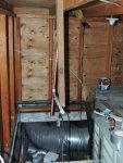
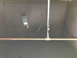
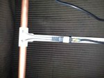
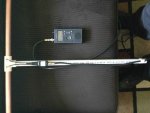
Hi all! Just finished making the OCFD from the RR wiki. I am just a guy that knows how to use a drill and a pipe cutter. I also enjoy scanning with my PSR800 and BCD396xt. Thought I would give this antenna a try and it was easy! Took longer to get the parts then it did to put them together. I mostly listen to the Portland Public Safety Radio System in Portland, OR and never have a problem hearing it. The signal is so strong, I could more then likely use a paperclip for an antenna! I wanted to make this because its something to do AND maybe I can pickup some new stuff. I am going to put it up in the attic and use some coax from an old DirecTv setup that is no longer in use.

That said, does anyone see any problems with my work? The plans are kind of basic, but I researched the forums for awhile and think I did it all right. Also, there is a signal booster/splitter up in the attic from an old TV antenna. Its a RadioShack Model: 1500321. Would it do me any good hooking up to it?

Thanks to everyone who reads this!

--Jon
 

Attachments

  • antenna1.jpg
    antenna1.jpg
    44.7 KB · Views: 2,083
  • Antenna2.jpg
    Antenna2.jpg
    59.3 KB · Views: 2,756
  • Antenna3.jpg
    Antenna3.jpg
    53.5 KB · Views: 2,396

popnokick

Member
Premium Subscriber
Joined
Mar 21, 2004
Messages
2,841
Location
Northeast PA
Wirelessly posted (Mozilla/5.0 (iPhone; CPU iPhone OS 6_1_3 like Mac OS X) AppleWebKit/536.26 (KHTML, like Gecko) Version/6.0 Mobile/10B329 Safari/8536.25)

Sa-weet! But with a meter like that you're more than a guy who "knows how to use a drill and a pipe cutter".
Remember to mount the antenna vertically... Doesn't matter which end up.
Regarding the splitter/booster. Try it with & without if you can. If you live in a dense RF area with paging transmitter interference and FM broadcast interference, the booster will make it worse. Or if what you listen to is already very strong you may notice overloading of the front end receiver stages of the scanner. OTOH, the booster may be just the ticket to pull in what you've never heard before.
I use mine in my attic with old TV coax and the splitter feeds two scanners. Yeah I know... a few dB lost in the splitter. My signal meters and my ears can't tell. Works great for what Iisten to.
 
Last edited:

JonDickson

Member
Joined
Aug 27, 2011
Messages
35
Location
NE Portland, Oregon
Wirelessly posted (Mozilla/5.0 (iPhone; CPU iPhone OS 6_1_3 like Mac OS X) AppleWebKit/536.26 (KHTML, like Gecko) Version/6.0 Mobile/10B329 Safari/8536.25)

Sa-weet! But with a meter like that you're more than a guy who "knows how to use a drill and a pipe cutter".
Remember to mount the antenna vertically... Doesn't matter which end up.
Regarding the splitter/booster. Try it with & without if you can. If you live in a dense RF area with paging transmitter interference and FM broadcast interference, the booster will make it worse. Or if what you listen to is already very strong you may notice overloading of the front end receiver stages of the scanner. OTOH, the booster may be just the ticket to pull in what you've never heard before.
I use mine in my attic with old TV coax and the splitter feeds two scanners. Yeah I know... a few dB lost in the splitter. My signal meters and my ears can't tell. Works great for what Iisten to.

Hi popnokick, thanks for the reply! I got the antenna all tucked away in the attic. Tried it on a TV antenna mast also, but it was no better than in the attic. Figured if I keep it inside I won't have to worry about grounding or wind issues. It could not fit better! The pitch of my roof is such that it wedges in between the roof and the floor perfectly, standing vertical. I also tried it with the booster but it made no difference. Just have it wired directly with one piece of coax. I am about 5 air miles from Portland International Airport and pick up just about everything. The tower is crystal clear but the planes on the ground are still kind of muddy. I can hear PDX approach but mostly just the planes, not the controller. Makes sense to me because they are up high and he is down low. Now I need to find some new stuff to listen to!

Also, I think what you are seeing in the picture is my big ugly PSR800, not a meter. I assure you, I know nothing about real radio stuff other then the few things I have picked up from trolling around here in the forums. Thanks again!

--Jon
 

popnokick

Member
Premium Subscriber
Joined
Mar 21, 2004
Messages
2,841
Location
Northeast PA
Wirelessly posted (Mozilla/5.0 (iPhone; CPU iPhone OS 6_1_3 like Mac OS X) AppleWebKit/536.26 (KHTML, like Gecko) Version/6.0 Mobile/10B329 Safari/8536.25)

That IS a scanner, not a meter! Was blurry on my iPhone and jiggly because I was riding the bus. Thought it was some flavor of MFJ Antenna Analyzer.
 

nanZor

Active Member
Joined
May 28, 2009
Messages
2,807
You did a good job. I recognize that RS 300:75 transformer and like it because it has isolated windings. And you didn't split the wires too far apart at the feedpoint - good.

After you get a feel for it, you may want to try your hand at the "shorty" version which is only 2-feet long on one leg, and 9-inches long on the other. This will improve the directionality down towards the horizon a bit on uhf and above, but vhf low may suffer.

Just remember that this is a very broad-band antenna, and may expose you to overload just like a discone can, so be prepared to use the ATTenuator if you have to.

Overall I see nice work.
 
Last edited by a moderator:

JonDickson

Member
Joined
Aug 27, 2011
Messages
35
Location
NE Portland, Oregon
Thanks Hertzian. Its been doing pretty good so far. No overload issues yet. I think tonight i am going to get down to trying to pick up some military air stuff. Who knows!

--Jon
 

LtDoc

Member
Joined
Dec 4, 2006
Messages
2,145
Location
Oklahoma
It certainly looks like it would work. It'd probably work much better if you get it outside that bus though. :)
- 'Doc
 

nanZor

Active Member
Joined
May 28, 2009
Messages
2,807
... trying to pick up some military air stuff. Who knows!

By all means have fun with it. If you get into civil / milair monitoring a little deeper, then the "shorty" of 2-feet / 9-inch legs is an improvement over the standard long one.

BUT, you have the tools and materials to do milair right with a fat dipole cut specifically for that band. All that would take is using a 9-inch tube on each side of the feedpoint, and ditch the transformer - just attach the center conductor of the coax to one side, and the shield to the other. That would end up being a wide-bandwidth dipole centering on 300 mhz.

The OCFD is fun for sure - but keep this note about the dipole in the notebook should you develop a taste for it.
 

dmg1969

Member
Joined
May 19, 2006
Messages
1,096
Location
Newport, PA
Looks good, Jon! I built one too and have it in my attic. Mine is on an angle due to the height restrictions, but it pulls in great. It is a nice alternative to an external mount and fun and easy to make.
 

JonDickson

Member
Joined
Aug 27, 2011
Messages
35
Location
NE Portland, Oregon
Thanks for the feedback everyone. I am interested in the "shortie" version for sure! I had to buy a 10' length of copper pipe and still have enough left to build it. Is it still broadband or will it just get the air bands? The big one is pulling in 800mhz public safety great. If I were to build the tuned antenna for air band how should I attach the stinger and shield? Screws also? Is it just a matter of stripping back the insulation and separating everything?

--Jon
 

popnokick

Member
Premium Subscriber
Joined
Mar 21, 2004
Messages
2,841
Location
Northeast PA
Wirelessly posted (Mozilla/5.0 (iPhone; CPU iPhone OS 6_1_3 like Mac OS X) AppleWebKit/536.26 (KHTML, like Gecko) Version/6.0 Mobile/10B329 Safari/8536.25)

Jon- read this thread here in this forum and pay special attention to hertzian's post , which explain that the shorty version of the OCFD reduce the high angle of radiation above 300 mHz that is present in the 18/48 version:
http://m.radioreference.com/forums/GetThread.php?t=267596&bat=
Otherwise, construction of shorty OCFD is same as regular.
 

JonDickson

Member
Joined
Aug 27, 2011
Messages
35
Location
NE Portland, Oregon
Well I swapped the long pipes out for short ones and made the shortie. So far, so good. Picking up some more stuff at the airport now. I can hear the planes on the ground, although through the fuzz. I can also understand PDX approach now. Good stuff! Thanks for the input, I have enjoyed messing around with things the last couple of days!

P.S.- Don't judge me based on the condition of my attic---its a mess. HaHa

--Jon
 

Attachments

  • Shortie1.jpg
    Shortie1.jpg
    75.4 KB · Views: 1,547

Techy

Member
Joined
Dec 21, 2005
Messages
75
Location
Long Island, NY
Is that RS transformer better than a Channel Master CM9444 300:75? And please explain the "isolated windings". Looking to put another OCFD up at a friends. He just purchased the Grove model. Thanks in advance. :)
 

nanZor

Active Member
Joined
May 28, 2009
Messages
2,807
Is it still broadband or will it just get the air bands? The big one is pulling in 800mhz public safety great.

It is still broadband. The original long version of the ocfd has a primary resonance around 88mhz - which could be bad if you suffer from FM broadcaster overload. The shortie has a primary resonance at around 150mhz which may lessen the FM broadcast problem if you have it. Being shorter, like popnokick mentions, is that above primary resonance, the lobes are closer to the horizon than the long version which is generally a good thing. I really don't make the long versions anymore and stick to the short ones.

If I were to build the tuned antenna for air band how should I attach the stinger and shield? Screws also? Is it just a matter of stripping back the insulation and separating everything?

The one I mentioned earlier for milair with 9-inch legs on each side is a classic dipole that has a natural impedance of 73 ohms, so no matching transformer is necessary to mate up with your usual 50/75 ohm coax cable. In the case of the ocfd, when you move the feedpoint away from the center, the impedance rises, and where we put it necessitates the use of a transformer to bring the impedance down closer to cable impedance.

For connecting to a classic dipole with equal-length legs on both sides, you just strip off some of the jacket and center insulation, and most will want to use some sort of solder or crimp spade or circular lug to neaten things up under the screws. Save the transformer for some other project.
 

nanZor

Active Member
Joined
May 28, 2009
Messages
2,807
Well I swapped the long pipes out for short ones and made the shortie.

Nice pic! I wish my attic was that clean.

I'd place the ocfd between the two vertical wooden beams I see - maybe just a U-clamp or two of some sort around the pvc screwed into the right hand vertical beam.

Heck, you could even just hang the thing with fishing line, twine, what have you since there isn't any human traffic or wind to deal with. In a pinch I've been known to use dental floss. Keeps the attic minty-fresh. :)

Ground comms and even tower comms can be tough even when you are close to the airport.

Remember the direct-connect equal-length transformerless dipole I mentioned for milair with 9" legs on each side? You could do the same for civil air by making those legs 22 inches on each side.

For a nice performance comparison here, do some listening with your shorty mounted between those beams and take s-meter readings. Use the attenuator if you have to if the s-meter is pegged. Write down some s-meter readings.

Now mount a classic transformerless dipole for civil air with the 22 inch legs on each side, and repeat the s-meter readings. It will either blow your mind with enhanced performance, or you may find the shortie ocfd is doing ok in your situation for civil air.

The center fed dipole is one of the "reference" antennas upon which other antennas are compared to, so if you have the time and materials, this might make an interesting study.
 

nanZor

Active Member
Joined
May 28, 2009
Messages
2,807
Is that RS transformer better than a Channel Master CM9444 300:75? And please explain the "isolated windings". Looking to put another OCFD up at a friends. He just purchased the Grove model. Thanks in advance. :)

I can't really say if the RS model is better than the Channel Master. I know that the OTA tv-guys that homebrew those monster uhf-high tv arrays use CM a lot, but there seem to be differences in attenuation among brands at those very high frequencies. Down here below 500mhz, the difference between a CM and RS may not be a big deal. I'm sure they would scoff at the RS, but then again, they are not scanning, but dx'ing TV at ultra high freqs.

This forum may be of interest to OTA high-def viewers doing the homebrew thing:
Local HDTV Info and Reception - High Def Forum - Your High Definition Community & High Definition Resource

It may provide additional transformer/balun info that us scanner guys might want to upgrade with our ocfd's, or ST2's etc.

The way to test for isolated winding is with a multimeter and make sure there isn't any continuity between the input and output leads. Many share a common ground. While this isn't a showstopper, it helps a bit to not have any physical continuity between input and output.

I don't know what transformer/balun the Grove antenna is using. It would be interesting to test for continuity. AND, just upgrading to a CM may not be as big a deal down at the typical scanning frequencies, but if I had one, I'd certainly test it to see especially if I was monitoring 800mhz a lot.
 
Last edited by a moderator:

dmg1969

Member
Joined
May 19, 2006
Messages
1,096
Location
Newport, PA
hertzian, I have a question for you about your statement about his not having split the wires of the balun too far apart. If you remember, I made one of these back in February (http://forums.radioreference.com/bu...67-my-homemade-off-center-dipole-antenna.html) and actually attached mine to the copper outside of the PVC fittings. I know you had also mentioned in my thread about possibly moving them to under the screws going into the PVC. If I decided to do that (I would have to crawl back up into the attic), would I notice a difference? All in all, I am happy with the performance as is.

Thanks!

P.S. Don't want to hijack, just curious since I have seem you mention it twice when discussing the OCFD antenna.

You did a good job. I recognize that RS 300:75 transformer and like it because it has isolated windings. And you didn't split the wires too far apart at the feedpoint - good.

After you get a feel for it, you may want to try your hand at the "shorty" version which is only 2-feet long on one leg, and 9-inches long on the other. This will improve the directionality down towards the horizon a bit on uhf and above, but vhf low may suffer.

Just remember that this is a very broad-band antenna, and may expose you to overload just like a discone can, so be prepared to use the ATTenuator if you have to.

Overall I see nice work.
 
Last edited:

JonDickson

Member
Joined
Aug 27, 2011
Messages
35
Location
NE Portland, Oregon
Hertzian...you are just a knowledge database! Thanks so much for all your input. I am thinking about trying the civil air dipole now. Just have to not spend all my allowence this week as my wife is the bread winner around here and I am Mr. Mom. (Don't judge) I have a simple soldering iron and a coax stripping tool. I hope i am not asking too many questions. When I strip the coax and seperate stinger/shielding I should make them the same length? Just strip the insulation off of the stinger a quarter inch or so then twist the shielding into a wire? Do I have to put any kinda of insulation over the exposed shielding? Just hold the wires against the pipes and cover with plain old solder? I know I am asking alot.......

--Jon
 

nanZor

Active Member
Joined
May 28, 2009
Messages
2,807
I know you had also mentioned in my thread about possibly moving them to under the screws going into the PVC. If I decided to do that (I would have to crawl back up into the attic), would I notice a difference? All in all, I am happy with the performance as is.

I did see that and it is a great project write-up. I'm not sure you'd see a major performance increase, and if you are happy with it as is - end of story! :)

However, the reason for not splitting the transformer wires too far apart is to prevent the leads from turning into additional lengths of wire that act as extensions to the antenna elements themselves, (changing the resonant points) rather than acting more as a parallel transmission line right up to the feedpoint. Bringing the copper tap-in points closer to the ends of the tubing is also recommended, rather than attaching them 2 inches or so inward like it looks in the pic.

That's not to say that your antenna is bad - far from it! I'm not sure that a little more precision would lead to a very noticeable difference, but if you have the time....

One problem with the ocfd, even if you have a perfectly straight transmission line coming out of the transformer to the feedpoint, is that the antenna is so asymetrical, that the transformer and cable shield itself will become a part of the antenna so to speak, so total precision here may not be justified.

I'd just do it for good engineering practice - at least as far as an ocfd goes. There does come a point where putting too much into "optimizing" an ocfd becomes questionable, so if it is working ok now great. Tell you what - if you don't do vhf-low, maybe try shortening each of the legs by half, and see what happens!
 
Status
Not open for further replies.
Top