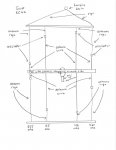
Huh, I never looked at the canonical ST-2 until today. Some great threads about it here. Gave me a brainstorm. ")
To put it simply, it is a very nice fan-dipole with a 4:1 (300-75 ohm) balun/transformer. Maybe that's too simple, but that balun caught my eye.
What other simple broadband diy antenna uses a 4:1 transformer? Yeah, the OCFD. But this isn't about that - it has been discussed forever.
But where does the OCFD go wrong where the ST-2 fan dipole goes right?
1) The elements are fed in the center, rather than offset, thus the balun can actually do a bit of common-mode rejection. The total imbalance of the ocfd means that the balun is overwhelmed, and cannot do much common-mode filtering. In fact, that is what makes it work on low-band - using the coax braid as much of the antenna.
2) On a related note, the fan-dipole being balanced, also means that the 4:1 balun can do a more accurate job of impedance step-down, whereas the massively offset ocfd means a LOT of reactance that really skews transformer impedance efficiency.
3) Mostly important is the fact that the fan dipole has varying element lengths, which means that you have a much better chance of having a decent radiation / reception angle, vs the ocfd's "vertical long wire" effect that basically points the lobes straight up above vhf.
4) Broad-band is helped for pure non-resonance with the 4:1 transformer, where impedances can go very high. Both the fan-dipole and ocfd share this feature, BUT again, the varying element lengths of the fan-dipole make it a winner.
So how about testing a simple fan dipole with 3 elements (6 total for dipole configuration) of varying lengths and a 4:1 transformer balun? Could it be this simple?
I'll have to think it over for what element lengths to use. I'd probably shoot for simple "halving" of lengths, like 36 / 18 / 9 inches to start and play with that. Hmmmm.. it all depends. Note that I'm NOT trying to shoot for a 50-75 resonant impedance at the center of the bands I'm interested in, as the 4:1 transformer would take that down to 12.5 ohms for example. I'm purposely cutting things off-tuned for a higher overall impedance, and hoping the lobes don't get too wacky.
So instead of trying to duplicate an ST-2, how about a *custom* fan dipole? As we've seen with the ocfd, mere low impedance matching does not a good antenna make when the radiation angle is straight up.
For an rx-ony setup, perhaps a slightly lossy imperfect 4;1 tv-type transformer might be the easiest practical solution, rather than trying to make it all perfect as if I'm trying to make it transmit-worthy -- ie radiation angle is more important than trying to achieve a 1:1 swr with lobes pointing straight up!
Hmm - have to think before I cut. Opinions please - good or bad!
Last edited by a moderator: