Yagi-Uda antenna mystery failure

Status
Not open for further replies.

KDS4444

Member
Joined
Mar 4, 2018
Messages
11
I am trying to access a local public Internet access point at 2.4 gHz using a homemade Yagi-Uda antenna. I built the first such antenna using 2mm copper rod and wooden boom with 8 directors, and in the end it worked, but my signal strength was only about -67 to -79 dBd so I decided to try building a larger/ longer antenna with 12 directors and a more durable and weather-resistant acrylic boom hoping to get a signal that was consistently at least around -65 decibels. I am using a program called NetSpot vers. 2.8.1.600 to get signal readings, and I used a program called Yagi Calculator version 2.6.18 to compute the positions and lengths of my various elements and their distances apart for both antennas (see attached PDF for the results of the Yagi Calculator). With the second antenna finished, I was very optimistic about its performance.

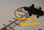
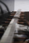
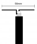
Well, it works, but the second antenna is decidedly much less effective at reaching its access point. Instead of an expected improvement in gain, I have had a significant reduction (signal is now down to -75 to -96 decibels) and I frequently cannot reach the Internet through it at all. I had carefully measured the length of each director using a steel calipers with accuracy down to hundredths of a millimeter for both antennas, and the elements are accurate to within 0.1mm of the length that the Yagi Calculator had told me they should be. I used this same calipers to measure the distance between each element on both antennas, so I am pretty confident their positions are also quite accurate. I used a drill press to cut the holes in the acrylic bar to ensure that they would be very straight and very consistent. I have had an eyeball look at the final alignment of the elements, and they look like they are lining up nicely and are tapering the way they should be all along both sides of the length of my boom. My folded dipole is a little less graceful on the second antenna than on the first, but is the correct width according to the Calculator and is still quite close to the correct shape and size (one thing I have never understood: should the hole in the boom for the driven element be placed along the same line as the holes for the directors and reflector? This is where I have placed mine in both antennas).

I am using the same 802.11 USB wireless LAN card for this second antenna as I did for the first. The card was originally a "19-gain" omnidirectional antenna that I modified and converted into a directional Yagi-Uda. My computer has no difficulty detecting the card when I plug the USB cable into it.

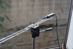
The boom on the second antenna is connected to a camera tripod which holds the antenna about four feet out my apartment window (which looks somewhat precarious, see photo). The previous boom was attached to a hollow metal tube out this same window. I can't think of anything about the boom support structure that should be affecting my antenna's reception, but then I am very much a novice here.

I am including photographs of this second build, now that it is complete. Does anyone have any ideas about why I might be experiencing such a reduced level of signal quality? I realize that the 12-director antenna has a narrower angle of reception, and that I must aim it more accurately at its target in order to get a decent signal, but I am pretty sure I am aiming it as well as I had done before (my target is about 400 feet away). On the second antenna, the card is located somewhat closer to the dipole and is over the reflector, since there was no more length on my boom to attach it-- I don't know if the location of the card should be having any affect here or not).

Also: while I was able to use a continuous piece of wood for the first antenna, for the second one I had to use two pieces of acrylic. They are attached to each other with two short (1/2" long) stainless steel pegs (would these be affecting reception? They do not contact any of the directors). Each element of the second antenna is held in place with a few drops of UV reactive adhesive (the wooden boom's elements did not require any adhesive) and I have capped each element with a short length of heat-shrink tubing so that their ends would be protected (turns out that 2mm copper rod when cut precisely with a dremel tool at a right angle produces some sharp edges).

I am assuming there must be something structural about my second antenna which is causing its reception to be so much weaker, but cannot figure what it must be (e.g., am wondering if somehow the acrylic boom is affecting the signal, though I thought this would be invisible to the incoming radio waves). Am hoping that by describing the build and showing others some photographs of it, someone will be able to look at it and say, "Here's your problem right here..." and explain what I need to fix. Any takers?? After so much precision of execution on my end, it is especially disappointing to be greeted with a penalty rather than an improvement. I am a man out of ideas.
 

Attachments

  • InkedIMG_3691_LI.jpg
    InkedIMG_3691_LI.jpg
    39.8 KB · Views: 392
  • IMG_3665.jpg
    IMG_3665.jpg
    42.9 KB · Views: 432
  • IMG_3687.jpg
    IMG_3687.jpg
    26.2 KB · Views: 387
  • yagi calculator results.pdf
    83.7 KB · Views: 70

prcguy

Member
Joined
Jun 30, 2006
Messages
15,368
Location
So Cal - Richardson, TX - Tewksbury, MA
There will be a big difference in element lengths between a metal boom and insulated boom. You are using insulated wire which will be a different length than an insulated wire but much of your elements are buried in plastic and that will affect length some. Did your Yagi calculator take this into consideration?

Your folded dipole is more of a loop than a dipole and not lined up with the director or reflector elements. You should either squash the loop into an actual folded dipole or move the loop so its more in line with the other elements.

How are you getting from the 50 ohm coaxial output of the LAN card to the antenna? A folded dipole is around 200 ohms impedance and its hard to say what impedance your loop is or if its resonant where you want it to be. I hope you not using a TV transformer to feed the loop.
prcguy
 

cmdrwill

Member
Joined
Mar 30, 2005
Messages
3,984
Location
So Cali
. I hope you not using a TV transformer to feed the loop.
prcguy

Looks like a balun attached to the 'folded ' element is in the way/signal path in the photo.

"local public Internet access point at 2.4 gHz ", is that horizontally polarized?

Yagi antennas are better at transmitting than receiving due to the small capture area. The good old oven rack with the batwing elements do a better job at receiving.

And then there is the dish antenna .... one of prcguy's favorites.
 

prcguy

Member
Joined
Jun 30, 2006
Messages
15,368
Location
So Cal - Richardson, TX - Tewksbury, MA
Yea, I saw a dish once but it was too far away to touch. Do they need a balun?

Looks like a balun attached to the 'folded ' element is in the way/signal path in the photo.

"local public Internet access point at 2.4 gHz ", is that horizontally polarized?

Yagi antennas are better at transmitting than receiving due to the small capture area. The good old oven rack with the batwing elements do a better job at receiving.

And then there is the dish antenna .... one of prcguy's favorites.
 

KDS4444

Member
Joined
Mar 4, 2018
Messages
11
Thank you for the responses! Here's more info (and more disclosure of my own ignorance, bear with me):

1.) I don't think my wire is considered insulated-- it was raw copper wire when I installed it, and the only insulated wire is that which leads from the driven element to the wireless card (which is inside the black plastic oval box-thing at one end of the antenna). Or did you mean, "You are using UN-insulated wire which will be a different length than an insulated wire"? Let me go with that assumption. No, my calculator did not ask about insulation for any of the wiring I used. A few of the other calculators I checked out also did not mention the effects of insulation. I've never seen a photo of a Yagi-Uda that HAD insulated wires, but I suppose these must exist. My understanding had been that since the wiring was not itself conductive, it would not have any meaningful effect on the performance of the antenna. But...??

2.) ....****. I just figured out one of my mistakes. The Yagi calculator had given me dimensions for a SINGLE dipole as well as for a DOUBLE one, but I only saw the dimensions for the SINGLE one. Damn it! My dipole should INDEED be much less loop-like! Argh! Obviously I need to fix that before I go any further. My entire problem might possibly be fixed by this alone.

3.) Is the local access point polarized? I have no idea. I had read somewhere that Yagi antennas should usually be mounted "sideways" for reasons having to do with polarization, but I do not think my access point is working with a Yagi antenna at all and am not sure how to determine its polarization.

4.) The LAN card is attaching to the antenna via the two wires you see on the dipole-- i.e., at the top of the "loop" where the gap is located. This is where I have seen other Yagi constructions attach their wires to the driven element. Is this not where such wires should be going? They are only a few inches long. The card then connects to my computer via a USB cable that is itself about 8 feet long.

Obviously, I need to entirely recreate my dipole here, which, now that I read my instructions more carefully, should be made out of 141mm of copper wire rather than the 58mm I have used here. It's a wonder that I get any signal at all. With regard to that, my question remains: is my current "loop" dipole at least mounted in the correct spot? (i.e., along the same line as the directors and the reflector?). Please advise on that, if you would.

I will now have to complete this little repair and get back to y'all if I still get pathetic results. Which I am now hoping I will not. I will also be certain to move all of the parts of my LAN card out of the way of my signal path. No TV transformers were involved in the creation of this antenna. My thanks for the guidance thus far.
 

Attachments

  • dipole.jpg
    dipole.jpg
    9.8 KB · Views: 340

Ubbe

Member
Joined
Sep 8, 2006
Messages
9,046
Location
Stockholm, Sweden
Yagi antennas are better at transmitting than receiving due to the small capture area. The good old oven rack with the batwing elements do a better job at receiving.

He's using the antenna for internet WiFi, both transmit and receive.
At that frequency everything is so tiny in wavelenght that it is difficult to do anything yourself that will work, without having any sort of antenna analyzer.

I wouldn't try to build a WiFi antenna when there are complete ones with coax for less than $20.
https://www.ebay.com/itm/New-2-4Ghz...ctional-Antenna-for-Router-Modem/162925458405
s-l225.jpg


I would look into this type of antenna for point-to-point access:
s-l225.jpg


/Ubbe
 

KDS4444

Member
Joined
Mar 4, 2018
Messages
11
You've convinced me. Based on the advice I have gotten here, I guess I am going to scrap this antenna and replace it with a cheap one from eBay. Less work, more effective. Thanks, though.
 

paulears

Member
Joined
Oct 14, 2015
Messages
789
Location
Lowestoft - UK
If you calculate the lengths of the elements then these are end to end measurements. You have yours protruding through the boom, so the 10-12mm or so that is inside the boom wrecks it. If you attach the elements to the top of the boom - they work, and the boom simply interferes with the radiation pattern a little. Through boom elements do work - but are better on VHF frequencies and below, where the inside the boom measurement is a small proportion of the overall length. For 2.4Ghz, the short length makes the inside boom portion a large part of the 'whole'.

Antennas are dual function devices. The polar pattern and gain figures are the same for receive and transmit as the science is the same. A resonant antenna with say 6dBd gain has 6dBd gain on receive AND transmit. Capture area is exactly the same!
 

FKimble

Member
Joined
Jul 14, 2014
Messages
513
Location
Newnan, GA
Why don't you try your original antenna but rotate it 90 degrees and see if the different polarization helps you signal strength?

Frank KK4YTM
 

popnokick

Member
Premium Subscriber
Joined
Mar 21, 2004
Messages
2,841
Location
Northeast PA
The newest, most recently installed WiFi systems & antennas are multi-polarized.... so polarization of the client device antennas (cellphones, laptops, etc.) is much less critical. And the same is true of the newer external antennas for client device use found on eBay etc. However, the OP may have no way of knowing which antenna type and polarization is being used by the access point. So if the OP purchases an antenna that is known to be specifically polarized (i.e. vertical or horizontal but not both).... then it would be advisable to try changing the position of the client device antenna to change the polarity. If however a multi-polarized antenna is used on the client it will make little difference which polarity is in use by the AP.
 

prcguy

Member
Joined
Jun 30, 2006
Messages
15,368
Location
So Cal - Richardson, TX - Tewksbury, MA
I'm still concerned about how the dipole is fed. The LAN card is most likely 50 ohm output impedance with a circular connector and you somehow have two parallel wires coming off the LAN card.

If the intended folded dipole has roughly 200 ohm impedance, there needs to be something that transforms the unbalanced 50 ohm impedance of the LAN card to the 200 ohm balanced impedance of the antenna. Are you sticking wires into the antenna connector on the LAN card to feed the dipole?
prcguy

Thank you for the responses! Here's more info (and more disclosure of my own ignorance, bear with me):

1.) I don't think my wire is considered insulated-- it was raw copper wire when I installed it, and the only insulated wire is that which leads from the driven element to the wireless card (which is inside the black plastic oval box-thing at one end of the antenna). Or did you mean, "You are using UN-insulated wire which will be a different length than an insulated wire"? Let me go with that assumption. No, my calculator did not ask about insulation for any of the wiring I used. A few of the other calculators I checked out also did not mention the effects of insulation. I've never seen a photo of a Yagi-Uda that HAD insulated wires, but I suppose these must exist. My understanding had been that since the wiring was not itself conductive, it would not have any meaningful effect on the performance of the antenna. But...??

2.) ....****. I just figured out one of my mistakes. The Yagi calculator had given me dimensions for a SINGLE dipole as well as for a DOUBLE one, but I only saw the dimensions for the SINGLE one. Damn it! My dipole should INDEED be much less loop-like! Argh! Obviously I need to fix that before I go any further. My entire problem might possibly be fixed by this alone.

3.) Is the local access point polarized? I have no idea. I had read somewhere that Yagi antennas should usually be mounted "sideways" for reasons having to do with polarization, but I do not think my access point is working with a Yagi antenna at all and am not sure how to determine its polarization.

4.) The LAN card is attaching to the antenna via the two wires you see on the dipole-- i.e., at the top of the "loop" where the gap is located. This is where I have seen other Yagi constructions attach their wires to the driven element. Is this not where such wires should be going? They are only a few inches long. The card then connects to my computer via a USB cable that is itself about 8 feet long.

Obviously, I need to entirely recreate my dipole here, which, now that I read my instructions more carefully, should be made out of 141mm of copper wire rather than the 58mm I have used here. It's a wonder that I get any signal at all. With regard to that, my question remains: is my current "loop" dipole at least mounted in the correct spot? (i.e., along the same line as the directors and the reflector?). Please advise on that, if you would.

I will now have to complete this little repair and get back to y'all if I still get pathetic results. Which I am now hoping I will not. I will also be certain to move all of the parts of my LAN card out of the way of my signal path. No TV transformers were involved in the creation of this antenna. My thanks for the guidance thus far.
 

KDS4444

Member
Joined
Mar 4, 2018
Messages
11
In order to connect the LAN card to the dipole, I removed its original antenna, an omnidirectional helix that had two wires connecting it to the LAN card, and replaced those connections with two new wires that I then soldered to the gap space of my dipole. That seemed straightforward enough to me, but clearly there is something I am not understanding there.

On another note: I tried removing all of the directors and the reflector from their holes, and mounted each of them (but not the driven element) along the top of the acrylic bar. Their positioning is somewhat less precise, but I have their order correct and they are still pretty straight. What I have as a result is the worst reception I have yet experienced through it. Maybe if I move the dipole up to the same level as the other elements, the antenna would receive the signal better, but I am stunned at how poor the reception has now become.

I have also replaced my old loop-like dipole with one that more resembles and is still the correct length of a more usual flattened circle. So far, this has, if anything, contributed to the decline in reception. One Yagi calculator I reviewed suggested I should be making this dipole out of 0.4mm wire, without regard to the 2mm rods I have already used all along the antenna. Does that make any sense? I have some 0.5mm brass wire, should I give that a try here??

(also: have now ordered a "real" antenna from ebay, should be here this week, not soon enough).
 

KDS4444

Member
Joined
Mar 4, 2018
Messages
11
Have now uploaded new image of Yagi showing new dipole and placement of all elements except dipole along top of acrylic boom. Worst reception over... I can move the dipole up there too, but will there be any point?
 

Attachments

  • IMG_3718.jpg
    IMG_3718.jpg
    36 KB · Views: 246

paulears

Member
Joined
Oct 14, 2015
Messages
789
Location
Lowestoft - UK
The helix is a complete antenna - and there are plenty of learned papers on impedance matching them, so I wonder if the problem here is that the impedance transformer you are using is simply totally wrong for the folded dipole - which normally needs a 4:1 balun to convert i9t to coax and 50Ohms.

As you're clearly ok at making things - why not use a bit of the wire you have to make a half wave unfolded dipole which will match the cable impedance - obviously there should really be a balun in there to convert the balanced dipole to unbalanced feeder - but if you knock up a dipole of the correct size and mount it on your boom - you might suddenly get a workable antenna that will at least prove the design is sound - then you could experiment with the folded dipole and proper matching?
 

KDS4444

Member
Joined
Mar 4, 2018
Messages
11
Thanks for the vote of confidence! Here is the principal barrier I am still facing:

Although I have read over the relevant Wikipedia article on baluns and will pretend to claim to know and understand what a transformer is, I really do not understand the function of a balun nor understand how to create one appropriate for this particular purpose. I have a sense that if I had ever actually studied electronics, this might come to me more intuitively. Alas, no. I understand what a wavelength is, and I understand what a half-wave dipole is in relation to that, and I understand what lambda means, and I grasp ohms of resistance... But I do not grasp how a coaxial cable affects antenna reception, and I do not know how to construct nor exactly where to place the mysterious "balun" component in relation to my other wires and parts here. Though I would like to learn, and if anyone were willing to tell me, I would be willing to reward them with photo evidence of my effort and hopefully a success story (?) of my antenna adventure! Any takers??
 

paulears

Member
Joined
Oct 14, 2015
Messages
789
Location
Lowestoft - UK
Knock this up. It's a half wave dipole for 2450MHz - but beware that it is compromised - it's the correct length, but has no balun at all. It can easily be made by soldering two bits of wire directly to the coax. It is a balanced device - but connected to an unbalanced feed. These actually work, but because the two sides of the feeder are different lengths and often materials, they did become part of the total system - currents flow in the feeder and stuff like that - so efficiency is down, and in a purely technical sense, they're poor.

The balun design used for microwave frequencies often uses etched pub tracks to make the transformer - heres a cheap typical one http://www.farnell.com/datasheets/1...40.1614367181.1520360183-406738446.1513936016

If you make this and add it to your antenna it should work ok on receive - the VSWR on transmit will be high so power lost. If this doesn't produce some improvement - then something is wrong with the design - maybe the measurements? It will do to show the system works as we don't quite know how your driven element is really being fed.

The design of baluns can often appear to be mysterious - Tonna, the French antenna manufacturer really confused me back in the late 70s with a halfway dipole driven element where the balun was a short link of aluminium shorting out the driven elements near to the centre. This was magic back then to me, and it makes no common sense at all. However, to RF, it's a tuned circuit, and current circulates and the design is still in use years later.
 

Attachments

  • dipole.jpg
    dipole.jpg
    61.8 KB · Views: 219

KDS4444

Member
Joined
Mar 4, 2018
Messages
11
Okay... Am trying to figure this out now. My present dipole has a gap between its two ends-- each end has been soldered to a wire, and the other end of each wire has then been soldered to my LAN card. I am still confused (and it is not your fault!) as to how this makes it an "antenna", since all I see is a flattened/ oval copper loop that seems to create a short circuit of some kind, but let's put that aside for the moment. You are suggesting that I close my gap with a piece of aluminum? I had a look at the chip-balun you mentioned, but although I can see what it looks like and can read its measurements, I cannot tell what it is made of and don't have any idea how it would connect to my antenna. Also, I should be clear about this: I have not used an actual coaxial cable anywhere in my current design. I have connected the card to the dipole with wires. I am getting the sense that the coaxial structure of a coaxial cable, however, has some kind of effect on the transmission and reception of the antenna (though I do not understand this, and maybe don't need to). I have never been altogether clear on whether I am aiming for "balanced" or "unbalanced" signals, or on how they affect the antenna's performance. As I said, I like to think I am basically competent with electricity, and I know how to read a multimeter and what capacitance is, but impedence escapes me. The distance from my card to the dipole is less than two inches: do I need to get a coaxial cable for such a short distance? And then... I insert a balun... between the coaxial and the dipole? And I should not use a tv coaxial to do this? (I have no wifi coaxial around anymore, though I used to). Am I getting closer? If I show you a photograph of the LAN card, will that help anything?
 

KDS4444

Member
Joined
Mar 4, 2018
Messages
11
And then there is this, which does not decrease my confusion: 2 4GHz Yagi Antenna

The dude in that video makes a Yagi antenna which seems to work rather well. All of his elements are cut the exact same length (mine are graduated), and each of his elements, including the driven and the reflector, are all exactly 30 mm apart (the distance between each of my own parasitic elements is also graduated, and my dipole sits much closer to the first parasitic than to the reflector). At no time does he mention a balun, though he does have a real coaxial cable. His elements are run through an aluminum tube are are obviously electrically connected to it, except for his dipole: his dipole is lentil shaped (never seen THAT before) and it is mounted so that his aluminum box tube runs more or less through the middle of the lentil-- he did not drill a hole in the box tube for the dipole.

It looks to me like he breaks nearly every rule I had come to understand about creating a 2.4gHz wifi Yagi antenna, but it seems to work just fine for him. Here I am, trying to use better materials (copper elements rather than aluminum; elements are fully isolated; distances and lengths of all elements are precisely graduated, etc.) and tools (drill press, not a hand drill; calipers measuring down to 100ths of a milimeter) but I am getting "diddly-squat" for reception when I am all done with it. What can he possibly be doing so right that I am doing so wrong?
 

KDS4444

Member
Joined
Mar 4, 2018
Messages
11
{...and it does add a bit of insult to injury to watch him dismiss as garbage the very antenna that I just bought on eBay and which I am expecting to get in the mail this week....)
 

paulears

Member
Joined
Oct 14, 2015
Messages
789
Location
Lowestoft - UK
So you have a small pcb that had some kind of antenna element attached to it, and this is gone and you are trying to make something new?

You have a big problem. You have no idea what type of antenna it was designed for - it could be almost anything. You really do need to do some research on the basics - balanced and unbalanced are two types of possible connections of equipment. In essence it's to do with symmetry. If you strip away accuracy and cleverness, your antenna has symmetry along it's axis. The driven element that emits and receives the data you are sending is also symmetrical, and can be as simple as two rods, emerging from the centre. It isn't right, but if you think back to your school physics lessons with a battery and a bulb connected with two wires, the current circulates. It comes out of one terminal, goes around and back, RF works differently. two short elements merging from the centre where they are driven can simply stop, or they can be folded back around and joined. Open or short circuit doesn't matter to RF, because it's electromagnetic energy, The circuit that drives it is designed for a short or an open circuit. One has a lower impedance that the other. Resistance wise, one is a short, the other and open circuit - but that matters little.Your problem is determining what your circuit is expecting. Then you can build the right thing, One warning - your pub allows transmit and receive, so getting the design wrong almost certainly means the effective power output will be much smaller than it should be, and that impacts performance. Whatever you are viewing the strength reading on - a computer? - cannot differentiate between TX and RX, so all our talk of coax, dipoles and receive only stuff needs scrapping - you are transmitting too.

If the pcb connects to the antenna directly, then it will probably be balanced. Coax, that you are not using is unbalanced. A centre core and a screen - not symmetrical. The balun we speak about simply converts one into the other. Try the length of wire I suggested and connect to those dangly wires.

I think your loop that goes around and back with the 5mm gap is unlikely to be remotely right in size, and it's well away from the plane of the antenna.

I assumed you knew more than you do - I'm sorry about that, but I fear you have attempted something far more advanced than you thought. Those dangly wires that come out from the circuit board - they Weill become part of the circuit, and can't just be dangled - they will try to radiate. I'm not sure we can really help you at a distance, we simply don't know what you know. You started to talk about coax, and I wrongly assumed you intended to use some. You've learned lots of little bits, but have linked them in a logical, but probably wrong way. at 2.4GHz you can't even use VSWR meters or the usual learning tools.

Perhaps you need to simply replace the antenna it was originally supplied with and use that. Yagis are normally coax fed, with a balun. microwave antennas can be made much simpler with helix types and these have circular polarisation too - but that's yet another subject, so let's pass for the moment.


You made a great job of the mechanical construction, but you have bodged the feeding of the driven element. The video with the micrometer measurements is a good example. Yours has very variable feeding arrangements - the two close together black wires from the pcb will be radiating at right angles to the rather strange shaped and spaced folded dipole. This is where your design needs work - and as you don't have any test gear, you can't do much apart from follow a proper plan - and as you are using a pcb based tx and RX unit - your driver part isn't that compatible. It probably has very little output power because of the poor matching, so the software seeing this assumes receive is as bad (which it will be) and your on-screen gain is very poor. You can't follow 90% off the plan, and then ignore the last bit. I've assumed your plan you followed had a coax output? Yours doesn't.
 
Last edited:
Status
Not open for further replies.
Top