• To anyone looking to acquire commercial radio programming software:

    Please do not make requests for copies of radio programming software which is sold (or was sold) by the manufacturer for any monetary value. All requests will be deleted and a forum infraction issued. Making a request such as this is attempting to engage in software piracy and this forum cannot be involved or associated with this activity. The same goes for any private transaction via Private Message. Even if you attempt to engage in this activity in PM's we will still enforce the forum rules. Your PM's are not private and the administration has the right to read them if there's a hint to criminal activity.

    If you are having trouble legally obtaining software please state so. We do not want any hurt feelings when your vague post is mistaken for a free request. It is YOUR responsibility to properly word your request.

    To obtain Motorola software see the Sticky in the Motorola forum.

    The various other vendors often permit their dealers to sell the software online (i.e., Kenwood). Please use Google or some other search engine to find a dealer that sells the software. Typically each series or individual radio requires its own software package. Often the Kenwood software is less than $100 so don't be a cheapskate; just purchase it.

    For M/A Com/Harris/GE, etc: there are two software packages that program all current and past radios. One package is for conventional programming and the other for trunked programming. The trunked package is in upwards of $2,500. The conventional package is more reasonable though is still several hundred dollars. The benefit is you do not need multiple versions for each radio (unlike Motorola).

    This is a large and very visible forum. We cannot jeopardize the ability to provide the RadioReference services by allowing this activity to occur. Please respect this.

Seeking information about the Radio Shack 48" Fiberglass Antenna

Status
Not open for further replies.

KK4HBW

Member
Joined
Apr 23, 2013
Messages
27
I'll present my system specifications before my question(s):

Components:
Radio Shack Adjustable 48" Fiberglass Whip Element for CB Antenna (PN: 21-974)
Radio Shack Chrome-Plated Spring CB Antenna Mount (PN: 21-1118)
Radio Shack Mobile CB Antenna Ball Mount Base (PN: 21-1115)

Installation:
The ball mount is affixed near the rear corner of a pickup truck bed, on the driver's side, approximately 3.5" below the rim of the bed walls. Approximately 10' of coaxial cable is routed through the driver's side pickup bed wall, then into the cab.

Measurements:
With the antenna at its lowest position in the compression coupling, on top of the 4.13" spring, I have a 51.5" overall length (or just about 1/8λ physical length, end-to-end). The ball mount adds another ~2", making it slightly longer than ideal for the center of the CB band (27.185 MHz), or so it would seem.

The SWR readings also lend credence to the theory that the antenna is currently tuned to a much lower frequency than 27.185 MHz (ch. 19):

26.965 MHz (ch. 1): ~1.1
27.185 MHz (ch. 19): ~1.5
27.405 MHz (ch. 40): ~2.4

Questions:
Before I take a hack saw or Dremel to this antenna, to shorten it, I need to know more about the antenna. Radio Shack has not published sufficient specifications, other than the fact that it is about 48" long. So, is this supposed to be part of a 1/8λ antenna, or is there a loading coil somewhere within, making it a 1/4λ (or other wave fraction)?

Second, if there is a loading coil, where is it? I don't want to go lopping that off...

Third, if you don't *know* the answers to my questions, what would be your best guess?

Thanks,
Mike.
 

KK4HBW

Member
Joined
Apr 23, 2013
Messages
27
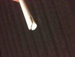
Here's a picture of the top, under the rubber cap. Does that look like a coil of some sort to you?

It's copper, two rows of "dots" on each side of that groove cut in it. It's either like that all the way up, in which case I could safely cut it from the top; or that it's only at the top, in which case cutting it at the top may ruin the antenna.
 

Attachments

  • image.jpg
    image.jpg
    32.6 KB · Views: 862

prcguy

Member
Joined
Jun 30, 2006
Messages
15,368
Location
So Cal - Richardson, TX - Tewksbury, MA
The antenna is a 1/4 wave resonant and judging from the tightness of the windings at the top (dots that are coils cut through with a saw) its probably top loaded.

Bottom out the antenna in the mount which will tune it for the highest freq it can do in its current form then saw a little off at a time to center the SWR dip in the middle of the band. If you go a little too far you can always raise the antenna in the mount to add length.

Its unusual to see an antenna like this tuned by cutting down into the whip through the coils and that works fine but I would cut across the whip so unused metal and fiberglass is removed. Currently the top of the antenna starts at the bottom of the existing cut.
prcguy
 

LtDoc

Member
Joined
Dec 4, 2006
Messages
2,145
Location
Oklahoma
There are two things I would change if it were mine. First, I'd get all of the antenna above the bed rail. That means that ball-mount too. If it's partly below the bed rail (metal) then it's electrical characteristics are changed, not good. The second thing would be to get rid of that spring, which increases the antenna's length thereby lowering it's 'resonant' frequency. I think that would solve the cutting of the antenna.
Yes, those 'dots' indicate that the thing is a helically wound (long coil) antenna. That winding, or coiling, increases the inductance of the antenna which means it can be shorter than a typical 1/4 wave length, which is why it's only about half the length of that 1/4 wave antenna at 11 meters. (Decreasing the length of an antenna also decreases it's radiation pattern, effectiveness, so doesn't make it 'better' except for convenience (ain't hitting stuff).)
- 'Doc

(A 'shorty' antenna is certainly better than no antenna at all, so if it 'works' for you, then why not?)
 

k3cfc

Silent Key
Joined
Feb 27, 2011
Messages
715
Location
Beavertown Pa.
There are two things I would change if it were mine. First, I'd get all of the antenna above the bed rail. That means that ball-mount too. If it's partly below the bed rail (metal) then it's electrical characteristics are changed, not good. The second thing would be to get rid of that spring, which increases the antenna's length thereby lowering it's 'resonant' frequency. I think that would solve the cutting of the antenna.
Yes, those 'dots' indicate that the thing is a helically wound (long coil) antenna. That winding, or coiling, increases the inductance of the antenna which means it can be shorter than a typical 1/4 wave length, which is why it's only about half the length of that 1/4 wave antenna at 11 meters. (Decreasing the length of an antenna also decreases it's radiation pattern, effectiveness, so doesn't make it 'better' except for convenience (ain't hitting stuff).)
- 'Doc

(A 'shorty' antenna is certainly better than no antenna at all, so if it 'works' for you, then why not?)

This the best advice your going to find in here.
 

WA0CBW

Member
Premium Subscriber
Joined
Dec 8, 2011
Messages
1,635
Location
Shawnee Kansas (Kansas City)
Also consider that the manufacturer didn't know you were going to add 4-inches of spring to the antenna thus making the antenna 4 inches too long. Remember when the SS whips were 102" or 108 inches depending on if you used a 6" spring. I can't speak for Radio Shack but most fiberglass whips I have used did NOT use a spring. Also the physical length of an antenna can only be used to determine its wavelength if the antenna has no windings or loading coils.
BB
 

KK4HBW

Member
Joined
Apr 23, 2013
Messages
27
First of all, thank you to everyone for replying and trying to help. I really do appreciate it.

As I'm sure you all know, practically every mobile installation requires compromises. This antenna project began with a definition of the requirements (technical, practical, legal, and insurance), analysis of the vehicle (overall dimensions, distribution of metal mass, body conductivity, location of other electrical components and their potential for interference), and testing/experimentation with various antennas in various locations on the vehicle.

Everyone could go on and on with assumptions of my ineptitude, and I could go on and on about each choice I made and why, but simply put: I knowingly made several concessions in detriment to antenna performance; and in favor of accessibility, practicality, safety, security, and *local* product availability, while still meeting the application requirements. Every concession, the placement of this antenna mount down to a fraction of an inch, and the addition of the spring, has a reason. While it is not ideal from a radio perspective, it is ideal from a holistic perspective.

As for the replies that were specific to my question, Doc seems to think it's a continuously-loaded antenna, while prcguy seems to think that it's a top-loaded antenna. I finally decided that I'd wager the $$ I spent on the antenna and cut it down from the top anyway, and field test it.

From SWR indications, the antenna is now "tuned" for the middle of the band, and the SWR has dropped considerably across the entire band. A trucker passing through confirmed a 4-mile contact through moderate obstructions (residential and industrial). I can't be sure whether the limitation was his, mine, or both of our radios. One thing's for sure, though, this system meets my expectations.

When all is said and done, this is just intended to be a "daily driver" antenna. I always have the option to change the antenna out to suit the environment, circumstances, and future requirements.

Kind Regards,
Mike.
 

prcguy

Member
Joined
Jun 30, 2006
Messages
15,368
Location
So Cal - Richardson, TX - Tewksbury, MA
Nice to hear you got it working. My comment on top loading is based on the tight coils exposed in the cut and if the entire 48" was wound like that the antenna would probably resonate well below the CB band. Unless the mfr decided to make it a 5/8 wave or 3/4 but there would generally be advertising boasting about that. Not that it would make the antenna transmit any further....
prcguy


First of all, thank you to everyone for replying and trying to help. I really do appreciate it.

As I'm sure you all know, practically every mobile installation requires compromises. This antenna project began with a definition of the requirements (technical, practical, legal, and insurance), analysis of the vehicle (overall dimensions, distribution of metal mass, body conductivity, location of other electrical components and their potential for interference), and testing/experimentation with various antennas in various locations on the vehicle.

Everyone could go on and on with assumptions of my ineptitude, and I could go on and on about each choice I made and why, but simply put: I knowingly made several concessions in detriment to antenna performance; and in favor of accessibility, practicality, safety, security, and *local* product availability, while still meeting the application requirements. Every concession, the placement of this antenna mount down to a fraction of an inch, and the addition of the spring, has a reason. While it is not ideal from a radio perspective, it is ideal from a holistic perspective.

As for the replies that were specific to my question, Doc seems to think it's a continuously-loaded antenna, while prcguy seems to think that it's a top-loaded antenna. I finally decided that I'd wager the $$ I spent on the antenna and cut it down from the top anyway, and field test it.

From SWR indications, the antenna is now "tuned" for the middle of the band, and the SWR has dropped considerably across the entire band. A trucker passing through confirmed a 4-mile contact through moderate obstructions (residential and industrial). I can't be sure whether the limitation was his, mine, or both of our radios. One thing's for sure, though, this system meets my expectations.

When all is said and done, this is just intended to be a "daily driver" antenna. I always have the option to change the antenna out to suit the environment, circumstances, and future requirements.

Kind Regards,
Mike.
 

LtDoc

Member
Joined
Dec 4, 2006
Messages
2,145
Location
Oklahoma
If it's working, then it's working and that's good. Just for grins, how much of it did you cut off? I'm just wondering, no particular significance...
- 'Doc
 

KK4HBW

Member
Joined
Apr 23, 2013
Messages
27
If it's working, then it's working and that's good. Just for grins, how much of it did you cut off? I'm just wondering, no particular significance...
- 'Doc

I'm sorry, I just saw this reply. I started with 0.25" increments, then 0.125" increments, then the last few were 0.0625" increments. Not counting the inch (or so) of excess from R.S. bench tuning, I think I took off about 1.5" (give or take). I can't say the length of the wire or the number of turns removed, though.
 
Status
Not open for further replies.
Top