• To anyone looking to acquire commercial radio programming software:

    Please do not make requests for copies of radio programming software which is sold (or was sold) by the manufacturer for any monetary value. All requests will be deleted and a forum infraction issued. Making a request such as this is attempting to engage in software piracy and this forum cannot be involved or associated with this activity. The same goes for any private transaction via Private Message. Even if you attempt to engage in this activity in PM's we will still enforce the forum rules. Your PM's are not private and the administration has the right to read them if there's a hint to criminal activity.

    If you are having trouble legally obtaining software please state so. We do not want any hurt feelings when your vague post is mistaken for a free request. It is YOUR responsibility to properly word your request.

    To obtain Motorola software see the Sticky in the Motorola forum.

    The various other vendors often permit their dealers to sell the software online (i.e., Kenwood). Please use Google or some other search engine to find a dealer that sells the software. Typically each series or individual radio requires its own software package. Often the Kenwood software is less than $100 so don't be a cheapskate; just purchase it.

    For M/A Com/Harris/GE, etc: there are two software packages that program all current and past radios. One package is for conventional programming and the other for trunked programming. The trunked package is in upwards of $2,500. The conventional package is more reasonable though is still several hundred dollars. The benefit is you do not need multiple versions for each radio (unlike Motorola).

    This is a large and very visible forum. We cannot jeopardize the ability to provide the RadioReference services by allowing this activity to occur. Please respect this.

Wire an SCU-17 to my Radio?

Status
Not open for further replies.

Your_account

Completely Banned for the Greater Good
Banned
Joined
Jul 13, 2013
Messages
1,261
Location
.AT
I got an SCU-17.
The Manual is not that clear.
http://www.yaesu.com/jp/manuals/ol/SCU-17_OM_ENG_JPN_EAK21X700.pdf

albrecht-ae-5890eu_micbuchse_belegung.png
 

Your_account

Completely Banned for the Greater Good
Banned
Joined
Jul 13, 2013
Messages
1,261
Location
.AT
Yes but i dont understand how i have to wire it to the connector you see on the first post.
There is no other pugs (just an audio output on the back of the radio).
 

K7MEM

Member
Joined
Dec 16, 2013
Messages
433
Location
Swartz Creek, Michigan
Yes but i dont understand how i have to wire it to the connector you see on the first post.
There is no other pugs (just an audio output on the back of the radio).

The SCU-17 is really made for high end transceivers made for the amateur bands. The diagrams in the manual are not going to help you much, except for the one that is labeled "Interfacing to Other Transceivers", at the bottom of page 12. All of the SCU-17 features can't be used, but some can.

My interfaces are home made, but I have a HTX-100 that only has a microphone connector on the front and a audio output jack on the back of the radio. I have used for it for RTTY/psk-31 on 10 Meters.

First is the supplied USB cable (Type A male to Type B male). This should connect from the SCU-17 to your computer. When you connect this cable up, your computer should be able to see the "USB Audio Codec", which is the audio interface within the SCU-17. The USB cable also provides power for the SCU-17. You should also see a "Virtual COM" port on the computer. This will be used, in your case, for PTT (Push To Talk).

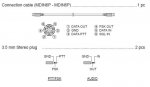
Then you need to connect the SCU-17 to your radio using the 3.5mm jack on the rear of the SCU-17 that is marked "Audio In/Out". The "Audio Out" (Sleeve and Ground) will go to the Audio Input on your radio. That would be Pin 1 (Audio) and Pin 5 (Ground) on the microphone connector.

Then the "Audio Output" from your radio (3.5mm connector on the rear of the radio) needs to connect to the SCU-17 "Audio In" (Tip and Ground).

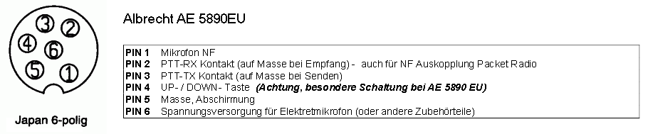
The problem is going to be with the PTT (Push To Talk) signal. The microphone for the AE5890 provides a ground for receive, Pin 2 (PTT-RX Contact) to Ground (Pin 5). When you go to transmit, the receive ground, Pin 2 (PTT-RX Contact), is removed and applied to the transmit pin, Pin 3 (PTT-TX Contact). So, when you disconnect the microphone, the receiver may not work, until you ground Pin 2..

You will probably have to use a external relay driven by the SCU-17 PTT signal. The relay could then provide the alternating grounds needed when switching from RX (Pin 2) to TX (Pin 3).

If necessary, I can probably draw you a diagram that will help explain the connections a little better. In the end, this connection is going to take a little experimentation and may not work the first time.

Note, at Alan Electronics, under the "Amateur Radio" link, is information for converting the AE5890 for Amateur Radio use.

Good luck with your project.

Martin - K7MEM
 

Your_account

Completely Banned for the Greater Good
Banned
Joined
Jul 13, 2013
Messages
1,261
Location
.AT
I will use it for CB only.
I make an Diagram is this correct?
Maybe you can help me a little with the wiring.
What kind of Cable do i need for the wiring?
 
Last edited:

jonwienke

More Info Coming Soon!
Joined
Jul 18, 2014
Messages
13,416
Location
VA
You have to know the wiring specification for the radio AND the microphone or you're wasting everyone's time.
 

jonwienke

More Info Coming Soon!
Joined
Jul 18, 2014
Messages
13,416
Location
VA
That is useless without knowing the pinout of the RADIO you intend to connect the microphone to.
 

Your_account

Completely Banned for the Greater Good
Banned
Joined
Jul 13, 2013
Messages
1,261
Location
.AT
without knowing the pinout of the RADIO you intend to connect the microphone to.
?!
albrecht-ae-5890eu_micbuchse_belegung.png

This are the connections. what is wrong with this?

EDIT: In English:
Code:
PIN 1  Microphone NF  
PIN 2  PTT-RX contact (on GND during reception) - also for  NF uncoupling packet radio 
PIN 3  PTT-TX contact (on GND during transmission)  
PIN 4  UP/DOWN button (caution, special circuit for AE 5890 EU) 
PIN 5  Ground, shielding 
PIN 6  Power supply for electrets microphone (or other accessories)
 
Last edited:

K7MEM

Member
Joined
Dec 16, 2013
Messages
433
Location
Swartz Creek, Michigan
That is useless without knowing the pinout of the RADIO you intend to connect the microphone to.

You must be having a bad day. The RADIO was listed in the original post. All of the documentations is readily available on-line, in multiple languages.

OP,

I will get back to you in the morning (my morning that is). I will look over your diagram.

Martin - K7MEM
 

jonwienke

More Info Coming Soon!
Joined
Jul 18, 2014
Messages
13,416
Location
VA
You must be having a bad day. The RADIO was listed in the original post. All of the documentations is readily available on-line, in multiple languages.

The item in the OP is not a radio, it's a USB interface to connect between a computer and a radio. The Albrecht is a power mic, not a radio.

Thanks for your feedback, though.
 

Your_account

Completely Banned for the Greater Good
Banned
Joined
Jul 13, 2013
Messages
1,261
Location
.AT
WTF?!
Again?
The "AE 5890" is a CB Radio with the Connector you see here:
albrecht-ae-5890eu_micbuchse_belegung.png

And with eh English translation:
Code:
PIN 1  Microphone NF  
PIN 2  PTT-RX contact (on GND during reception) - also for  NF uncoupling packet radio 
PIN 3  PTT-TX contact (on GND during transmission)  
PIN 4  UP/DOWN button (caution, special circuit for AE 5890 EU) 
PIN 5  Ground, shielding 
PIN 6  Power supply for electrets microphone (or other accessories)

You want the schematics for the PTT Mice here the are:
http://service.alan-electronics.de/...ht-Standardmikrofon-4197-auf-AE5890EU_R02.pdf

Sure the SCU-17 is a Sound modem. And I hope its clear to everyone to connect the USB to my Pc.
The Sound Modem have for me an very unusual Plugs and the Name of the Plugs are not easy to understand.
 

jonwienke

More Info Coming Soon!
Joined
Jul 18, 2014
Messages
13,416
Location
VA
When I googled the Albrecht, I got a link to the microphone, not the radio for some reason, and then you posted a link to the microphone. So I didn't understand what you were trying to do.

You can't just make a cable, you will need to make an interface card with a relay to properly activate the radio RX and TX. I would suggest an optocoupled solid state relay because they have low power consumption. Something like this:

PM1206C IXYS Integrated Circuits Division | Relays | DigiKey

You will need to connect the PTT signal and ground to the relay input, and the relay outputs to radio pins 2 and 3 so that the radio is receiving when it is supposed to receive, and vice versa. Radio pin 5 goes to relay out common. The relay only accepts 1.2VDC, so you will need a resistor and a zener diode on the relay input to prevent the PTT signal from damaging the relay.

If you want bi-directional data, you will need an additional cable going to the radio to get speaker audio and bring the voltage down to the correct level to go into the SCU-17.
 

K7MEM

Member
Joined
Dec 16, 2013
Messages
433
Location
Swartz Creek, Michigan
The item in the OP is not a radio, it's a USB interface to connect between a computer and a radio. The Albrecht is a power mic, not a radio.

Thanks for your feedback, though.

He looks, but he does not see, he reads, but does not comprehend.

You shouldn't be so condescending. When I first saw the original post, I also thought that there wasn't enough information and was ready to ask for more info. But as I read the follow up posts, I realized there was all the information I needed.

When I said, in my last post, that the "radio" was listed in the original post, I was not talking about the "link" to the SCU-17 manual. I know what a SCU-17 is and already had the manual. Again, you are misreading what was written.

To be more specific, right next to the connector diagram it says "ae5890eu". Try putting that in a google search and see what you come up with. I came up with a radio, not a microphone. Well, OMG, Albrecht makes things other than microphones. That lead me to manuals and the same connector diagram that was listed. Except that, I used the English version.

Martin - K7MEM
 

Your_account

Completely Banned for the Greater Good
Banned
Joined
Jul 13, 2013
Messages
1,261
Location
.AT
So maybe someone can help me with an schematic?
The friend who sold me that stuff dont help me to get it run.
 

Your_account

Completely Banned for the Greater Good
Banned
Joined
Jul 13, 2013
Messages
1,261
Location
.AT
and on the radio i have this plug:
albrecht-ae-5890eu_micbuchse_belegung.png


So which Number fit in what?
 
Status
Not open for further replies.
Top