• To anyone looking to acquire commercial radio programming software:

    Please do not make requests for copies of radio programming software which is sold (or was sold) by the manufacturer for any monetary value. All requests will be deleted and a forum infraction issued. Making a request such as this is attempting to engage in software piracy and this forum cannot be involved or associated with this activity. The same goes for any private transaction via Private Message. Even if you attempt to engage in this activity in PM's we will still enforce the forum rules. Your PM's are not private and the administration has the right to read them if there's a hint to criminal activity.

    If you are having trouble legally obtaining software please state so. We do not want any hurt feelings when your vague post is mistaken for a free request. It is YOUR responsibility to properly word your request.

    To obtain Motorola software see the Sticky in the Motorola forum.

    The various other vendors often permit their dealers to sell the software online (i.e., Kenwood). Please use Google or some other search engine to find a dealer that sells the software. Typically each series or individual radio requires its own software package. Often the Kenwood software is less than $100 so don't be a cheapskate; just purchase it.

    For M/A Com/Harris/GE, etc: there are two software packages that program all current and past radios. One package is for conventional programming and the other for trunked programming. The trunked package is in upwards of $2,500. The conventional package is more reasonable though is still several hundred dollars. The benefit is you do not need multiple versions for each radio (unlike Motorola).

    This is a large and very visible forum. We cannot jeopardize the ability to provide the RadioReference services by allowing this activity to occur. Please respect this.

IC-F121 Prgm Cable Pinouts?

Status
Not open for further replies.

Soundy

Member
Premium Subscriber
Joined
May 10, 2014
Messages
73
Location
Abbotsford, BC
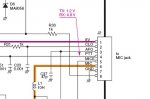
Looking at the cables for this on fleaBay, it appears it's a simple RS-232 serial connection on the RJ-45 mic connector - one ground, one RX, one TX, using pins 1, 7 and 8. So anyone know which pin is which? I can easily build my own, and it's not a big deal to figure out which is which through trial and error, but I figured it would be easier if someone could tell me what they are. :lol:
 

jeatock

Member
Premium Subscriber
Joined
Jul 9, 2003
Messages
599
Location
090-45-50 W, 39-43-22 N
Left to right on the front board, starting on the left outside edge looking at an assembled radio:

1- +8VDC
2- CLOne out
3- AFO out (requires internal mod for gated audio)
4- PTT <1.2V to TX, > 4.6V to RX
5- MICE ground
6- MIC in
7- GRND
8- CLone In and hanger

Pin 1 to ground will let the magic smoke out.

This pinout is the same for all land mobile radios with the RJ46 mic connector. They're all interchangeable.
 
Last edited:

Soundy

Member
Premium Subscriber
Joined
May 10, 2014
Messages
73
Location
Abbotsford, BC
Hmmm, interesting... The one eBay listing I found with a close-up of the plug, it appears to use 1, 7, and 8... but I suppose that could be 2, 7 and 8, which compared to the pinouts you listed should correspond to TX, GND, and RX.

Thanks, gives me something to work with :)

uploadfromtaptalk1424504525629.jpg
 

jeatock

Member
Premium Subscriber
Joined
Jul 9, 2003
Messages
599
Location
090-45-50 W, 39-43-22 N
2, 7 & 8 are correct.

These are from an F1821 voltage diagram that I had handy, but the J2 pinout is universal. HM-100 (old and new versions), HM-148, all "T" versions, and the SM-series desk mics are interchangeable.

Pin 8 is not identified in the voltage pic, but the trace is marked CLI elsewhere.
 

Attachments

  • micpinout.jpg
    micpinout.jpg
    21.6 KB · Views: 8,797
  • micpinout2.jpg
    micpinout2.jpg
    31.1 KB · Views: 4,117

Soundy

Member
Premium Subscriber
Joined
May 10, 2014
Messages
73
Location
Abbotsford, BC
Sweet, found the service manual... Now this is talking my language!

It also shows the Mic pinouts in at least two places, including CLI:

uploadfromtaptalk1424527326612.jpguploadfromtaptalk1424527337904.jpg
 

jeatock

Member
Premium Subscriber
Joined
Jul 9, 2003
Messages
599
Location
090-45-50 W, 39-43-22 N
Addenda

I happened to be working on one of the older F1020 radios today and after trying to clone it several times with my OPC1122 (senior moment) I remembered that these radios need the 3.5mm portable cable (OPC478) and RJ-45 adapter (OPC592) to communicate. Duuh!

F1020's along with FR3000's and others of the same vintage, use bi-directional data on pin 2 referenced to pin 7 ground. Pin 8 is only for the hanger-upper button contact.

Pin 7 to ground (sleeve on the 3.5mm), and pin 2 to ring on the 3.5mm. Tip and pin 8 are not connected.

The mics are still interchangeable.
 
Last edited:

Soundy

Member
Premium Subscriber
Joined
May 10, 2014
Messages
73
Location
Abbotsford, BC
Hmmm, so does that apply to the F121 as well?

Rigged up a cable to a USB/RS-232 adapter, tried it first with CLO connected to RD (out from radio, receive on serial) and CLI to TD (transmit on serial to in on radio), but got no response... swapped the data wires, and I get a solid LED on the adapter, and still no response. Trying to remember if that's normal or not, it's been years since I used one of these adapters to run PTZ cameras... seems to me the LED should be off and flicker to indicate data.

Anyway, probably going to switch it back... next question then is, what baud/parity/stop should this be using? Default for Windows is 9600 8N1, XON/XOFF flow control...
 

Soundy

Member
Premium Subscriber
Joined
May 10, 2014
Messages
73
Location
Abbotsford, BC
Hmmm looks like there may be a little more to this... found this in some searching:

3637707.jpg
 

Soundy

Member
Premium Subscriber
Joined
May 10, 2014
Messages
73
Location
Abbotsford, BC
This one shows a few different methods... looks like they got the pin numbers backward on the RJ jack, but otherwise, looks like it should work the way I've got it:

y4TjVqw.gif
 

Soundy

Member
Premium Subscriber
Joined
May 10, 2014
Messages
73
Location
Abbotsford, BC
Still no go with the last configuration. The adaptor does show a flicker of traffic when I hit Read, but after a couple seconds I get the "transceiver not responding" pop-up.
 

jeatock

Member
Premium Subscriber
Joined
Jul 9, 2003
Messages
599
Location
090-45-50 W, 39-43-22 N
The FR3/4000, F3/4xx, F1/2020 and other older radios are 2-7 only. Starting with the F5/621 and F1/221-series, 2-7-8 via OPC1122 became the standard; this has carried forward to F1/2721 and the F5/6xxx radios and FR5/6000 repeaters.

Looks like you are down to trial and error creating a OPC1122 clone. The front board chip looks for an instruction on CLI, then responds on CLO. If the chip doesn't decode the signal it won't send, or if it sends something may be garbling the data. Looks like Pin1 8V+ is used to power the cable components for plain RS-232 serial connections without power from the PC, but I am not positive. I only use the OEM USB cables, and since they have always worked (senior moments aside) I haven't bothered to explore the levels and rates. You might check to make sure some nimrod hasn't jumper-ed Pin8 to ground on the front board instead of soldering CP1 to disable hanger function.

Looking at the voltage diagram Pin8 CLI and hanger is biased high to look for the hanger button (or CP1).

One convenient thing about Icom is that I can go out with a full set of cables in one coat pocket, as opposed to lugging the box of adapters specific to individual models. Three USB cables glued together and a 3.5mm adapter cable tied to the end of the OPC478 will let you talk to everything they make. (Proviso: the new F9000 portables use a fourth connector.)

Consider it a challenge.


EDIT: Looking at the aftermarket reverse-engineered pictures above reminds me of why I always go back to the OEM voltage diagrams and board layouts. I can tell you that the same 9-pin cable (both RS232 and USB) works for all 9-pin radios - F30's, F50's and the new F3xxx's. Can't say about the 3.5mm on the ancient H10's, but F3's, F3G's, F33's and F11's through the brand new F30xx's and F1000's all speak over sleeve and ring on the same cable. The OPC592 adapter used for older mobiles (in my hand as I write this) only has wires on pins 2 & 7.

There is a reason I only have OEM cables - I can't afford the downtime trying to get anything else to work.
 
Last edited:

Soundy

Member
Premium Subscriber
Joined
May 10, 2014
Messages
73
Location
Abbotsford, BC
Well looks like the MAX232 doesn't do much more than voltage buffering of the RS-232 signal, down to 5V TTL levels (since RS-232 voltages CAN be much higher), but with a USB/serial adapter running 5V USB, voltage level shouldn't be a problem. The +8V in that circuit is just used to power the MAX232 (via a regulator), since RS-232 doesn't provide power.

I did check for the +8V, to make sure I had the RJ wired properly so I wouldn't fry anything - it's there on pin 1, and the hanger function works properly as well, so I don't think there's an issue there. I'll probably wire the thing back the way I had it at first, and fiddle with settings from there.

I remember there was some kind of issue getting my Baofeng USB cable working properly on my old laptop, although I think that was a specific driver issue for the USB/serial chip they used; this is a tried-and-true ATEN adapter... granted, this is also the first time I'm using it with 64-bit drivers, so maybe I'll find another serial device to test it on. I have some managed switches around that have serial console ports :)

Anyway, time to get to work... I'll keep this thread updated if I figure it out. I'm tempted to just order the proper cable, but keep futzing with this anyway because I don't want to let it beat me ;) I may pick up the MAX232 and regulator to make that circuit too.

Thanks for all the help!
 

jeatock

Member
Premium Subscriber
Joined
Jul 9, 2003
Messages
599
Location
090-45-50 W, 39-43-22 N
Had I bothered to look, icomamerica.com public knowledgebase article A81C634342 has the two mobile microphone pinout variations. Pin 1 is always to the left looking at the face of the radio.
 

Soundy

Member
Premium Subscriber
Joined
May 10, 2014
Messages
73
Location
Abbotsford, BC
Had I bothered to look, icomamerica.com public knowledgebase article A81C634342 has the two mobile microphone pinout variations. Pin 1 is always to the left looking at the face of the radio.

Yep, standard 8C8P... but with a non-typical use of the connector like this, I'm always leery, so I double-checked with the multimeter first :)
 

Soundy

Member
Premium Subscriber
Joined
May 10, 2014
Messages
73
Location
Abbotsford, BC
UPDATE:

Decided to give it another look with my straight USB-serial-RJ45 cable... just to check, I decided to meter the TX pin on the serial connector, and saw a steady 9.8V, dropping to about 9.5 when sending data via PuTTY.

Well, that's not right!

Then I figured I'd check the pins on the cable for my little Baofeng UV-5R, which uses the 3.5mm and 2.5mm TRS connectors: sleeve on the 2.5 is ground, ring is RX, and sleeve on the 3.5 is TX, so I metered GND-to-TX and got 0V at idle, and about 3.5V when sending from the terminal.

Hmmm, promising!

Soldered some clips on my RJ-45 cable, clipped to the TRS plugs, plugged into the radio, hit Clone on CS-F100.. SUCCESS!!!

Now that I've downloaded all the existing programming, I need to go through and figure out what some of the old frequencies are, and peruse the manual more to see if I want to change any of the other P1-P4 button settings, and learn some more about what this set can do :)

And eventually I imagine I'll just buy the proper cable...

bbeb7bfac66f0a5d51126cb2fa9bab3c.jpg
 
Last edited:
Status
Not open for further replies.
Top