
I had a couple questions about the rack construction for my computerized shack. (BTW, new pics coming later this week due to a new shelf for the desk and a couple radios added/changed.) Since I put the rack up on a table for some cleanup and maintenance I figured it was a good time to get some interior detail shots.
I use the ScannerMaster USB-1 to DB-9 converted cables to avoid the problems with the front serial ports on the scanners. They cost more but work great. The DB-9 is a much more physically secure connector than that little oddball port on the scanner.
On 2 of the scanners I have discriminator jacks, they are remoted out with an audio cable that I ran thru the USB hub's strain relief.
The entire box is pretty much self contained. The wires and cables going to the box are long enough to allow me to rotate it out for rear access or to clean the floor behind it.
There is one power cord, one USB cable, 2 antennas and the discriminator audio (which I rarely use on these radios these days). The box is set on a set of casters that allow me to roll it in or out as needed. I usually tuck the cabinet under the desk out of the way since I never need to touch the radios. I use ProScan to control them and can adjust the volume and squelch from the computer.
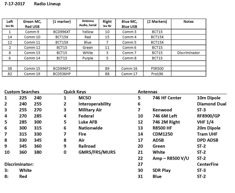
I keep track of the stuff with a cheat sheet that looks like this:
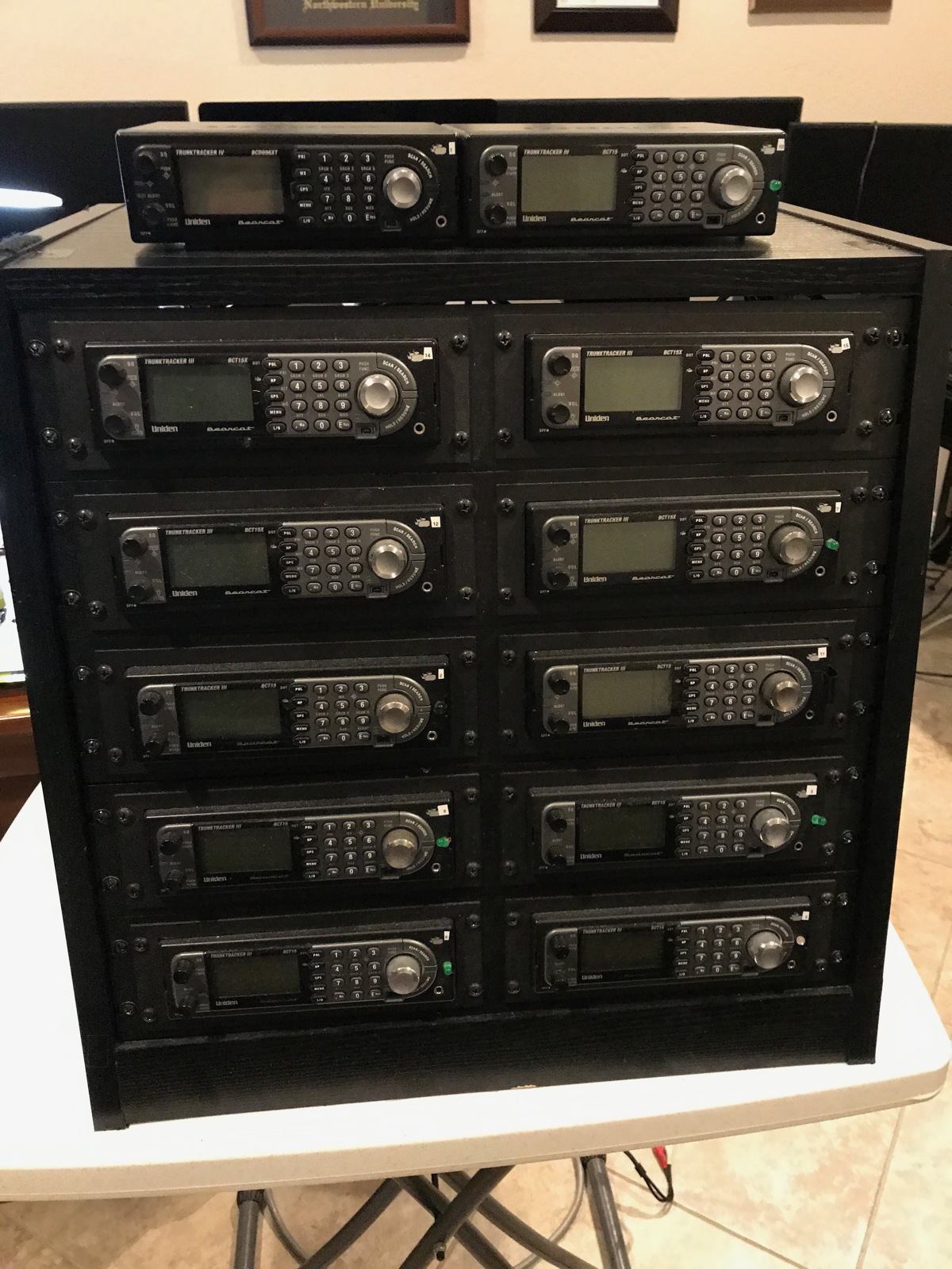
Here is the front of the rack showing the 12 radios 7 BCT15, 4 BCT15X, 1 BCD996XT). 10 radios are in the racks and 2 on top.
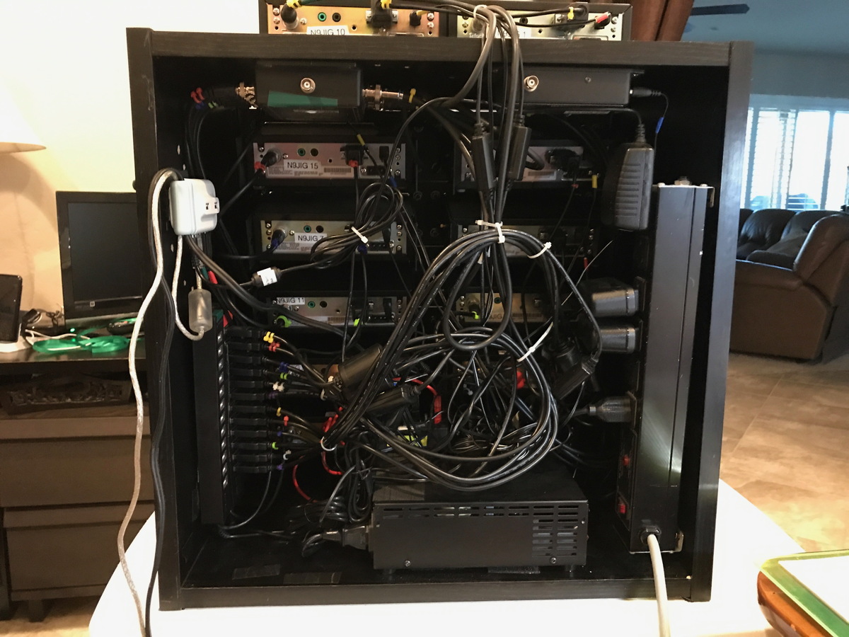
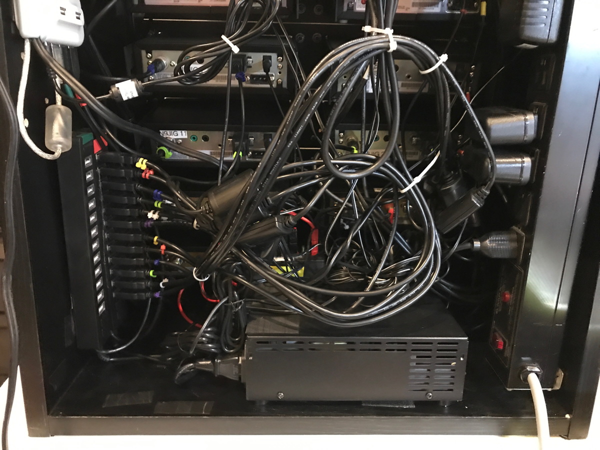
Next is the overall rear shot showing the rats nest.
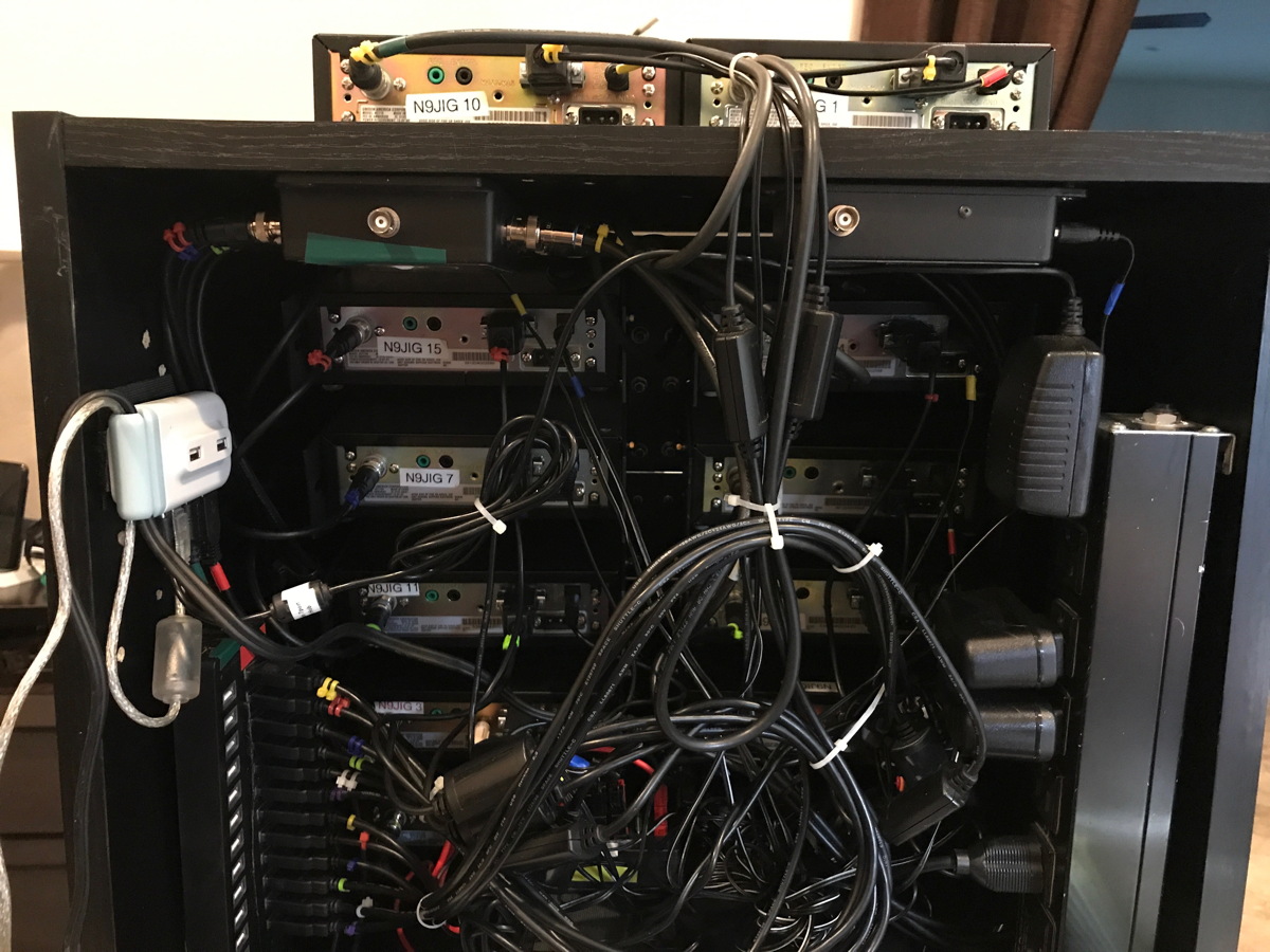
Here is a closer up view of the upper section. Notice the various color wire tags. One side has 2 tags and the other just one each. This allows me to tell which radio is connected to each cable. Each radio row has a color, each column has either 1 or 2 tags.
You can also see the little 4-port USB hub in which the 2 13-port ones connect into. This is a hold over from when I used the same case with a couple SDR sticks. I might delete this hub and just plug one of the 13's into the other but it has been working fine and allows me some flexibility for future expansion.
At the top of the case are 2 Stridsberg multicouplers. One is an 8-port, the other 4. This covers the 12 radios nicely.
Here is a closer up view of the lower section with the power supply, outlet strip and USB hubs. The rear 13-port hub is for the USB-Serial cables and the front one will be used for the sound cards when I decide on a solution for that. I already have the sound cards and cabling done but I am still trying to find an ideal solution for handling the audio. Currently I am just using the radio speakers which is fine for listening in the office. I would like eventually to be able to record the audio and maybe even make it available remotely.
I use the ScannerMaster USB-1 to DB-9 converted cables to avoid the problems with the front serial ports on the scanners. They cost more but work great. The DB-9 is a much more physically secure connector than that little oddball port on the scanner.
On 2 of the scanners I have discriminator jacks, they are remoted out with an audio cable that I ran thru the USB hub's strain relief.
The entire box is pretty much self contained. The wires and cables going to the box are long enough to allow me to rotate it out for rear access or to clean the floor behind it.
There is one power cord, one USB cable, 2 antennas and the discriminator audio (which I rarely use on these radios these days). The box is set on a set of casters that allow me to roll it in or out as needed. I usually tuck the cabinet under the desk out of the way since I never need to touch the radios. I use ProScan to control them and can adjust the volume and squelch from the computer.
I keep track of the stuff with a cheat sheet that looks like this:
Here is the front of the rack showing the 12 radios 7 BCT15, 4 BCT15X, 1 BCD996XT). 10 radios are in the racks and 2 on top.
Next is the overall rear shot showing the rats nest.
Here is a closer up view of the upper section. Notice the various color wire tags. One side has 2 tags and the other just one each. This allows me to tell which radio is connected to each cable. Each radio row has a color, each column has either 1 or 2 tags.
You can also see the little 4-port USB hub in which the 2 13-port ones connect into. This is a hold over from when I used the same case with a couple SDR sticks. I might delete this hub and just plug one of the 13's into the other but it has been working fine and allows me some flexibility for future expansion.
At the top of the case are 2 Stridsberg multicouplers. One is an 8-port, the other 4. This covers the 12 radios nicely.
Here is a closer up view of the lower section with the power supply, outlet strip and USB hubs. The rear 13-port hub is for the USB-Serial cables and the front one will be used for the sound cards when I decide on a solution for that. I already have the sound cards and cabling done but I am still trying to find an ideal solution for handling the audio. Currently I am just using the radio speakers which is fine for listening in the office. I would like eventually to be able to record the audio and maybe even make it available remotely.
