Vega Multicoupler - Amplifier Orientation

Status
Not open for further replies.

Twlighting

Member
Joined
Jul 24, 2014
Messages
47
Location
Los Angeles, CA
Took a gamble and picked up an older Vega 'Diversity Multicoupler' on the cheap to distribute signal from a common antenna to a few RX only radios here. It's comprised of 2 independent 1x4 signal paths. There's very little documentation about these units available, but they were likely used in conjunction with wireless microphone systems or wireless In Ear Monitors for performers.

Though the device itself was originally manufactured as VHF, it had a 10-1000Mhz P-Touch label on it, so pulled the trigger. Sure enough, the device was modified at some point with components covering the 10-1000Mhz range.

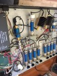
Tracing the path from the antenna connector, it appears that the output of the amplifier is sent through a high-pass filter and then onto the antenna. For distributing received signals I would have assumed this would be reversed, sending the amplified signal on to the power divider and subsequent attenuators. Does this look correct?

If this was intended to be used with IEMs (multiple transmitters into a single antenna) this configuration would make more sense to me, but the placement of the high-pass filter after the amplifier seems odd. It's also possible that my theory of operation of these units is incorrect.
 

Attachments

  • image0 (3).jpeg
    image0 (3).jpeg
    83.5 KB · Views: 109

majoco

Stirrer
Joined
Dec 25, 2008
Messages
4,285
Location
New Zealand
Are there two antennas? I can see the cable route from the near antenna through a larger blue thing which I assume is an HPF then off to one amplifier and a four-port combiner then to four small blue things to 4 BNC connectors. If there's only one antenna, where's the combiner after the other amp? No idea what the amplifier gain is, but would think that it's milliwatts output. Most multicouplers have a high pass filter at the antenna input to keep the AM BC band junk out - a 10kW transmitter just down the street makes all sorts of noises - then a low gain amplifier with just enough oomf to overcome the filter losses. The amplifier has to be a reasonably sturdy device so that it will pass a local strong signal without clipping followed by a splitter with good port-to-port isolation - your 4-port combiners may not do that very well but the last of the blue things are attenuators then you could be on to a winner especially if it was really cheap! Make sure the amplifiers aren't putting out too much power.

I have an eight port LF/HF multicoupler that has a massive input amplifier but only small gain that then splits off to the eight output isolation amplifiers. The input amp FET is a MRF136, a 15Watt VHF amp up to 400MHz and a hefty device it is too - you can leave your fingerprint on it if you touch it! It's only coasting along at 500mA 15volts in this circuit.
 

Twlighting

Member
Joined
Jul 24, 2014
Messages
47
Location
Los Angeles, CA
Yes, it's a little deceiving. In typical usage there are two antennas A & B for diversity reception. The multicoupler has 2 separate but identical distribution circuits. This creates 4 outputs for A and 4 outputs for B which are then in turn connected to the A & B antenna inputs on each piece of audio gear.

It's possible that this was also intended for In Ears/IEM usage where it's actually 4 diversity transmitters combined into a single pair of antennas, which might explain why the amplifier appears reversed.

As far as the signal path (assuming this RX) it's Antenna Connector > HPF > Amplifier > 6db Attenuator > Power Divider/Combiner > 3db Attenuator > Output Connector. What's strange to me is that the 6db attenuator is connected to the output side of the amplifier, and then the power divider to the input.

Makes sense on the HPF to cut out the AM interference. Seems like that's a good indication this was meant for RX.

Yes, this was $22 so not too bad of a price. Shortly after posting earlier, discovered the PSU was dead so that might explain it. After that's replaced I'll plan to fire it up and see what the performance is like, but sounds to me like your multicoupler would definitely run a few circles around this unit.
 

Ubbe

Member
Joined
Sep 8, 2006
Messages
9,042
Location
Stockholm, Sweden
It's also possible that my theory of operation of these units is incorrect.
Your picture shows a transmit combiner. 4 transmitter inputs are combined to one antenna. There's two of them. But then there's a power supply and the picture do not show any active devices that needs power. I guess there is more that wasn't captured in that single picture. Perhaps an unrelated receive circuit that are no part of the transmit design.

/Ubbe
 

Mike_G_D

Member
Joined
Dec 19, 2002
Messages
1,241
Location
Vista, CA
Well I certainly see active components! The amps appear to be Mini-Circuits ZFL-1000VH 20dB medium power amps ("Gain Blocks"). Those are the big things with the heat sink fins mounted on them and the obvious red and black DC power leads leading from them to the power supply.

From what I can see, I it looks to me as if it was used to combine two seperate groups of four low power source transmitters or exciters to one common antenna for each set of four (so two seperate antennas/some kind of RF sink or load). There appear to be two independent sections which are copies of each other. In other words you have two systems doing the same thing but independently, not connected to each other except through a common ground - both have 4 source inputs, each with a Mini-Circuits attenuation pad of unknown value (I cannot see the printing on them so I don't know what the value is but I would guess in the 3dB to 6dB range, maybe more, depending what kind of source power or level is expected at each of the 4 inputs) followed by the splitter/combiner which is another Mini-Circuits device but I can't read the model number (probably easy to guess using the Mini-Circuits catelog and noting the freq. range, etc.) whose common output then goes to another Mini-Circuits attenuation pad and thence to the "antenna" (??) or whatever RF load port.

From looking at the picture and the Mini-Circuits data sheet for the ZFL-1000VH I don't feel like it was intended for splitting a common antenna to multiple receivers given the medium power nature of the amp and its noise figure rating. It seems to me like it was intended more for the other way around - combining two sets of four low power RF transmitters into two seperate antennas or whatever loads.

Would help to have all of the model numbers for all of the Mini-Circuits components as we could then get an accurate estimate of what kind of level matching or gain was intended.

But, no matter what, I think you got a great deal since those seperate Mini-Circuits components can easily add up to more than what you paid for the thing! Those devices plus the enclosure, connectors, and cables could easily be used to create many usefull combinations!

-Mike
 

Twlighting

Member
Joined
Jul 24, 2014
Messages
47
Location
Los Angeles, CA
Interesting, that would explain the direction of the amplifier. Here's a slightly better photo with some annotations. The amplifiers are the only active components in the signal paths.

VegaDetail.PNG

Since a TX combiner won't do me much good, might reverse the amplifier and see what kind of performance that yields.
 

Twlighting

Member
Joined
Jul 24, 2014
Messages
47
Location
Los Angeles, CA
Mike, interesting on the amplifier and the implications that might present for RX applications. Here are the other components, all are Mini Circuits:

Amp: ZFL1000VH
Combiner: ZFSC-4-1
6db Attenuator: Cat-6
3db Attenuator: Cat-3
HPF: SHP-400
 

Mike_G_D

Member
Joined
Dec 19, 2002
Messages
1,241
Location
Vista, CA
Please provide the model number printed in the 4 way divider - I can't see it clearly but it looks like a resistive 4 way splitter so about 12 dB loss or so. So the full attenuation I see is 3dB + 12dB + 6dB = 21dB while the amp provides about 20dB of gain so a net result of around -1dB or so loss between each "input" and the common "output".

Edit: given the splitter model number my calc above was too high by 6dB loss-wise. See my later replies.

So pretty much, for all intents and purposes, two seperate unity gain/loss low power TX four port combiners, I think.

I don't currently see a 4 way BNC connector style resistive splitter on the Mini-Circuits website, only SMA style is comming up but it should be about similar specs.

-Mike
 
Last edited:

Mike_G_D

Member
Joined
Dec 19, 2002
Messages
1,241
Location
Vista, CA
Sorry - we "crossed posted" each other. I see you have provided the model numbers, thanks!

Ok, so the splitter is 6dB of loss meaning a net of about +5dB of gain total for each of the two systems.

Otherwise, the same - likely for low power TX combining.

-Mike
 

Mike_G_D

Member
Joined
Dec 19, 2002
Messages
1,241
Location
Vista, CA
And that filter looks like it was intended to pass only frequencies above about 395MHz so UHF and above. For whatever that is worth.

Still - lots of good parts!

-Mike
 

Twlighting

Member
Joined
Jul 24, 2014
Messages
47
Location
Los Angeles, CA
Makes sense - thanks for doing the math on the components. Indeed, lots of good parts for other things down the road.

Now, if I were to go down the path of trying to rearrange the components to create a receive multicoupler, I'd imagine I go directly from the 4 inputs/outputs to the combiner > HPF > amplifier > 6db Att > 3db Att > 3db Att > Single input/output. Seems like this would net me out at +2db.

Naturally I'd still be at the mercy of the amplifier specifications not being ideal for RX, but perhaps there's still some value in giving it a go?
 

Mike_G_D

Member
Joined
Dec 19, 2002
Messages
1,241
Location
Vista, CA
The way I would probably do it for a single antenna to multiple seperate receivers with ONLY the components provided in the box would be:

Using ONLY one section (one amp) for 4 receivers:

Source in (i.e. "antenna") --> Amp (20dB gain) --> 6dB pad --> 6dB pad --> 4 way splitter (loss of 6dB) common input (so total of 18dB of attenuation) --> finally to recievers attached to each of four outputs on the splitter. You have a small 2dB gain but that is good - just enough to overcome the loss of the splitter plus a weency bit. You could try replacing the second 6dB pad with a 3dB pad to get a net 5dB gain but I wouldn't go much beyond that.

I would not use the HPF UNLESS I was only interested in receiving above 400MHz.

BUT, I might decide to use the second amp and remaining pads plus the HPF for the second section so that I would have one for broadband and one for >400MHz use. In that case I would put the HPF between the antenna and the second amp (or first amp if that is all you are interested in).

But many combinations possible.

You could cascade the two splitters to get 7 outputs but then you have to carefully arrange the pads to get the output levels where you want. With only what is in the box you'd have to settle for some receivers getting a bit more gain than ones on the second downstream splitter.

I would not cascade the two amps - too much gain. Either use only one or use the second one for a seperate multicoupler arrangement like I outlined above (say for only >400MHz use if you elect to use the HPF).

The amps might not be LNA amps most would choose for receive use BUT their specs might be acceptable, even preferrable, in really high level metro RF saturated areas!

Good purchase overall, I think!

-Mike
 
Last edited:

Ubbe

Member
Joined
Sep 8, 2006
Messages
9,042
Location
Stockholm, Sweden
Now, if I were to go down the path of trying to rearrange the components to create a receive multicoupler,
The amplifier are terrible for receive. Get a ZX60-P103LN+ or something similar that has 0,5dB noise figure and P1 of 22dBm and IP3 of 40dBm at a 15dB gain. The ZFL1000VH has 5dB noise and its P1 and and IP3 are worse at 27dB and 38dB as the gain are 22dB, so take off 7dB from those values when comparing to a 15dB gain amplifier. You can stick a $25 circuit board PGA103+ amplifier in that box and get the same specs as with the ZX60-P103LN+ PGA103+ PGA103 wideband LNA Low Noise Amplifier assembled PCB, RTL SDR | eBay

/Ubbe
 

cmdrwill

Member
Joined
Mar 30, 2005
Messages
3,984
Location
So Cali
That may be a antenna coupler for a diversity receiver for wireless microphones.
Four channels and two antennas.
 

prcguy

Member
Joined
Jun 30, 2006
Messages
15,366
Location
So Cal - Richardson, TX - Tewksbury, MA
What you have is a receive mulitcoupler that's been hacked up and the amplifiers are in backwards. In stock condition these are very common for wireless mic receive systems and it has no use for mic transmitters as they are run independently and are never combined then amplified. There are a bunch of attenuators to level out the gain so its close to unity and that's another reason its not a transmitter combiner plus the amplifier output levels are way too low for any useful transmitter combining unless you want about 0dBm for each transmit carrier not including the loss in each attenuator.

I don't know what amplifiers were in there originally but the ZFL1000 series is a gain block with an atrociously high noise figure around 6dB, not something that you would consciously use as a receive preamp or in the front end of a receive multicoupler.

So in my opinion its completely useless as a receive multicoupler the way it sits but you did get probably 10X the value in used parts than you spent, so good deal!
 

Twlighting

Member
Joined
Jul 24, 2014
Messages
47
Location
Los Angeles, CA
Thanks for the insight all - yes, it's definitely a strange piece in it's current configuration.

If this were in fact a transmitter combiner similar to this unit:

TXCombine.PNG
Would there be any logic to padding the input to the amplifiers? Maybe to whack down the signal so as to not overload the amplifiers with their marginal P1 specs? As far as the amplifiers themselves, would they actually be appropriate for transmitter combiner applications despite the high noise figure? Or just a cheaper way that someone chose to get the job done? Then and again, PRCguy mentioned the low overall output, so maybe not.

In any event, like the idea of stabbing in a PGA103 amp, along with cascading the other set of outputs and balancing with the pads as needed. Thanks for the assistance.
 

majoco

Stirrer
Joined
Dec 25, 2008
Messages
4,285
Location
New Zealand
Well, an attenuator is also a matching device too, so if the input device is not quite 50ohm or whatever, the attenuator will bring it closer - the pads in the combiner will also benefit too.

I'm still puzzled by the actual use of this device. If it's going to be used for a live stage musical or something where all the artists are listening to the sound stage from the individual singers/talkers in stereo (two channels?) then there's got to be an easier method. Why generate an FM RF signal for each audio microphone and then mix them together? Unless the incoming RF is on four different frequencies of course and the headsets are tuneable so you can listen to one input or a stereo pair. Surely you've already generated the RF - just send to an antenna or a loop around the stage. Little stereo low-power transmitters are common in the VHF FM band and will transmit on a selection of frequencies so why not up in the 400MHz band. I have one going here 24/7 connected to an MP3 player and a 4Mb SD card with 700 or so singles on it. Mind you, that little mini-circuits amp box will give out +25dBm which is about 316mW in 50ohms but then they knock it back by -6dB - might be a bit of matching and protection.

Aha - I think you may be right - look at this blurb from RF Venue.... the same one as you found above....


Are there no manufacturers markings on your box? I wonder if it might be a bootleg copy of something much more expensive.

Hmmm - there seem to be lots of these on sale....


Twlighting

Member
Joined
Jul 24, 2014
Messages
47
Location
Los Angeles, CA
Yes, usually IEMs are used to provide a dedicated mix to artists in lieu of stage monitors. Usually it's a very specific mix of whatever vocals and instruments are needed by the artist, depending on the size of the show. Sometimes multiple performers will share a mix/frequency but those that can afford it like to have the ability to have each mix independent.

I believe most of the wireless microphone and IEM gear is limited to below 50mW TX power without special licensing. Perhaps these ZFL1000VH amps fit the bill for that?

Yes, looks like there are more on Ebay, and you've found one that still turns on! The only thing that peaked my interest on my unit was a P-Touch label affixed to the front that indicated 10-1000MHz, which meant it might be viable for my wideband RX needs. Wonder if that one on the link is an original config.
 

prcguy

Member
Joined
Jun 30, 2006
Messages
15,366
Location
So Cal - Richardson, TX - Tewksbury, MA
I said before its not a TX combiner its a horribly designed receiver multicoupler. If the amplifier is rated 25dBm out and you have 4 channels then at full output you would have 4.1dBm available for each carrier. Then there is the 6dB pad, another 6dB in divider loss and another 3dB pad leaving you with -10.9dBm out for each carrier. Then you would never run multiple carriers at full power because that amplifier will produce massive IMD, so subtract another 10dB to put it in a range where its only a minor IMD generator and now you have -20.9dBm per carrier. That's not enough to get across the street without a high gain antenna.

Its a botched receiver multicoupler and probably why it was dumped on Ebay. It can't function for any purpose the way its wired as received.
 

Ubbe

Member
Joined
Sep 8, 2006
Messages
9,042
Location
Stockholm, Sweden
The amplifier can output a total of max 50mW of power to the single antenna from 4 transmitters of 10mW each being combined and seem to match the recommendation for RF Venues TX combiner. That bad noise figure doesn't matter as it is not for recording and it might be a digital modulation as well. It's probably for in-ear monitoring for 4-8 musicians and stage performers.

" Unless you are using your IEMs across a football field you almost never want to run them at full 50 mW power levels. 30 mW or better 10 mW will provide better performance and less interference."


/Ubbe
 
Status
Not open for further replies.
Top