interesting J-pole variant

kc5uta

Member
Joined
Jul 18, 2011
Messages
109
Location
Shiner Tx.
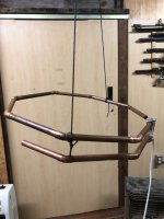
Had a weird (probably over caffeinated) idea pop into my head the other day. What if you took a regular J-pole antenna, and bent it into a halo antenna?
So I did. I made a regular copper pipe J pole, tuned it to 1:1 swr at 144.5mhz. Marked the points, then hit it with the tubing roller, made it into a halo, that has a 1/4 wave tuning stub vs the usual halo gamma match.
things noticed:
1. it was it was no longer "flat " at 144.5, but now flat at 152.300 (ish) with some variation noted when changing the spacing with the loop ends (pretty much like a halo)
2. feed point stayed close to the same spot
3. horizontal orientation was omnidirectional ( no noticible signal strength change on rotation )
4. when oriented vertically and turned it was directional, I assume perpendicular to the loop.
Unlike a halo (a dipole center fed with a gamma) this one turned out to be essentially a 3/4 wave end fed loop (i guess) with a 1/4 wave stub.
That said, I have no idea what the pattern or effectiveness would be horizontal or vertical. tried google to see if there was anybody else that tried this design, see what they thought.....worthless.
all i got was stinking J-pole/slim Jim links, and ads trying to sell me loop or j-pole antennas, the further down i went the more off topic it became....google sucks :-(
next time I build one Ill make it about 15% longer +/- to account for the resonance shift, go from there. Dave Kc5uta
 

DeeEx

Member
Joined
Aug 13, 2018
Messages
164
Location
New England
If I’m hearing you correctly, it sounds a lot like Stico’s attempts to make a low profile VHF-high mobile antenna, circa 1990. Underneath the Coolwhip container-sized housing was the antenna. Picture an NMO stub in the center, with a short vertical section, holding a horizontal washer/flat arc type affair. Tuning was done by moving a set screw somewhere between the mount and the feed point of the horizontal portion, if I recall correctly.
 

kc5uta

Member
Joined
Jul 18, 2011
Messages
109
Location
Shiner Tx.
this was one was too big for a radome cover antenna, (all i found on that topic) but thanks for the feedback. When I make the next version (without it looking too "krunky" hi hi) Ill post some pictures.
 
Last edited:

merlin

Active Member
Joined
Jul 3, 2003
Messages
2,503
Location
DN32su
Basically, you are turning a J-Pole into a Halo.
The characteristics all change. The Halo needs a counterpoise. think a dipole bent into a circular shape.
The elements will be a slightly different length and the radiation pattern changes from horizontal to about
33° upward.
Best advice here is plenty of reading in the ARRL antenna book. Both types are covered in that.
Cheers.
 

kc5uta

Member
Joined
Jul 18, 2011
Messages
109
Location
Shiner Tx.
Basically, you are turning a J-Pole into a Halo.
The characteristics all change. The Halo needs a counterpoise. think a dipole bent into a circular shape.
The elements will be a slightly different length and the radiation pattern changes from horizontal to about
33° upward.
Best advice here is plenty of reading in the ARRL antenna book. Both types are covered in that.
Cheers.
pretty much... but finding any actual documentation online specifically for that process in particular is a exercise in frustration. but yes it's basically an end fed 1/2 wave (ish) antenna, I'm guessing the 1/4 wave section is acting in that fashion???? So far ive only used the mfj analyzer on it, haven't put any real RF through it. When I do, i'll make sure there is a good choke involved, i'm sure the rf back in the shack would be ugly without it
 

kc5uta

Member
Joined
Jul 18, 2011
Messages
109
Location
Shiner Tx.
update made another one out of 2/0 house wire scrap I had, measured the short section at about 25 inches and the long section about 70 inches. Ran it in a piece scrap pex pipe ( to stabilize the wire shape into a circle), literally taped the short section along the pex parallel to make the "J". stripped an appropriate amount of insulation for the coax contact points...tuned like a charm. When I have one photo worthy built ill post a picture or three..
 

kc5uta

Member
Joined
Jul 18, 2011
Messages
109
Location
Shiner Tx.
Not quite the final version. Still in the prototype phase, but you'll get the idea. I used 1/2 inch copper pipe, 7" sections and standard 45 degree elbows to give it the octagonal look. Lessons learned so far.
1. The feed points tune like a standard J-pole.
2. I plan on cutting the sections at least 7.5 to 8 inches. (both long side and the "J" to give you plenty of trimming on the end piece for tuning)
2. A non conductive spacer at the end of the "J", such as plexi or delrin etc. to maintain the spread at the end is critical. less than an inch spacing change at the tip will change your resonance wildly.
3. Also much like a standard Halo antenna, the gap between the tuning end and the tip of the antenna as it curves back on itself needs to be fixed from moving, before or after final tuning is done, or will de-tune it.
4. Just like a "J" pole, you can add a support or mounting pipe without affecting the antenna (in this case another 2 foot copper pipe was attached to the T fitting I used at bottom of the "J" perpendicular to the antenna) Ill post pictures on the final version soon.
5. a copper end cap adds enough length to affect tuning as well.

Once I've finished with the final version the tuning part will most certainly NOT be hose clamps holding on the coax (lol)
end result was it tuned 1:1 at the target frequency of 144.5mhz, the diameter was roughly 19-20 inches across, with a gap of about 2 inches at the end near the tuning section. I have no idea what kind of pattern it will have, but I know it's horizontal and roughly omni. More to follow once I've finalized it........Dave
 

Attachments

  • j-loop 1.jpg
    j-loop 1.jpg
    67.1 KB · Views: 28

nd5y

Member
Joined
Dec 19, 2002
Messages
11,281
Location
Wichita Falls, TX
I have no idea what kind of pattern it will have, but I know it's horizontal and roughly omni. More to follow once I've finalized it........Dave
Just remember if you mount it on a mast and rotate the mast to try to determin the pattern you will be changing the position of the antenna and that can make the received signal strength can vary a lot even if the radiation pattern is a perfect circle.
The axis of rotation needs to be the center of the octagon not the mast.
 

kc5uta

Member
Joined
Jul 18, 2011
Messages
109
Location
Shiner Tx.
Just remember if you mount it on a mast and rotate the mast to try to determin the pattern you will be changing the position of the antenna and that can make the received signal strength can vary a lot even if the radiation pattern is a perfect circle.
The axis of rotation needs to be the center of the octagon not the mast.
Oh im sure if it was mounted next to the tower you'd get the cardoid or similar pattern. I plan on having it up well away from it, in the clear for at least a wavelength ....but good point
 

kc5uta

Member
Joined
Jul 18, 2011
Messages
109
Location
Shiner Tx.
well....finally got the antenna up in the air...and nobody is on 144.200 at 2200 on a tuesday .....bummer
good news is once a carefully trimmed it, it was 1:1 at 144.200
 
Top