PRO-2025 antenna circuit board problem

Status
Not open for further replies.

GTR8000

NY/NJ Database Guy
Database Admin
Joined
Oct 4, 2007
Messages
15,482
Location
BEE00
Somehow, there suddenly seems to be an internal short on the circuit board antenna connection. Basically, if I put an ohmmeter between the chassis ground and the center conductor of the antenna jack, I'm getting conductivity between them. I've desoldered and removed the antenna jack but am still showing the same problem, so it's definitely an issue on the board itself. Checked all the soldering to make sure nothing is touching, and it's all good.

Could this be a resistor or something that went bad and is stuck open, causing this? Anyone ever run across something like this before?
 

pro92b

Mutated Member
Premium Subscriber
Joined
Jun 27, 2002
Messages
1,910
Somehow, there suddenly seems to be an internal short on the circuit board antenna connection. Basically, if I put an ohmmeter between the chassis ground and the center conductor of the antenna jack, I'm getting conductivity between them. I've desoldered and removed the antenna jack but am still showing the same problem, so it's definitely an issue on the board itself. Checked all the soldering to make sure nothing is touching, and it's all good.

Could this be a resistor or something that went bad and is stuck open, causing this?

No, an open resistor reads infinite resistance.

Anyone ever run across something like this before?

Yes, the antenna connection should read a low resistance to ground. The inductor connected between those two points will read as a near short circuit at DC, but not at high frequencies.
 

GTR8000

NY/NJ Database Guy
Database Admin
Joined
Oct 4, 2007
Messages
15,482
Location
BEE00
Thanks for the reply, but could you translate that into dummy for me please? :D

The scanner was receiving great up until to a few days ago, when reception went way down and I was only getting local or strong signals. While I was running a check of the coax and antenna, I happened to stick just the center conductor of the coax into the scanner jack, and reception improved immediately. Once I connected the coax shield, right in the toilet again. When I put the ohmmeter on the antenna end of the coax, sure enough it was showing conductivity between the center conductor and the shield. That's when I pulled the scanner apart and realized it wasn't the coax or jack shorting out, but something on the board itself.

Question is, how do I fix this? :confused:
 

pro92b

Mutated Member
Premium Subscriber
Joined
Jun 27, 2002
Messages
1,910
I don't think there is anything wrong with the radio. The antenna or cable seems more likely at fault.
 

Mike_G_D

Member
Joined
Dec 19, 2002
Messages
1,241
Location
Vista, CA
antenna circuit

What you need to understand is that their are elements involved in RF design that look like a dead short at DC but present very different characteristics at high frequencies. An inductor will present a very low DC resistance typically but will present a much higher AC impedance at high frequencies. Your ohmmeter cannot "see" this. You would have to use a reactance meter or a network analyzer to fully "see" what the inductor presents, impedance-wise, to a high frequency RF signal.

A typical antenna matching circuit could very easily have shunt inductors as part of its design. If so and one of the inductors is shunted across the antenna port input then you will "see" a near dead short at the antenna terminal when using a DC ohmmeter. This is NOT an indication of a problem. You simply aren't looking at the antenna port with a device capable of "seeing" that port's characteristics at the designed for radio frequencies.

Having said that, you still may have developed a problem in the radio or you may have a cable or antenna problem. Without knowing the actual design of your receiver's antenna matching circuit we cannot know what "good" will be using any test instrument. Now, if you had measured the DC resistance before you had problems and noticed a high resistance whereas now you see a near short then that might be an indication of a problem. But without that "before" data we simply can't be sure. If I were to look at your receiver's circuit board at the antenna port I could likely deduce what the matching circuit is composed of in terms of its circuit elements. If I saw no inductors shunted to ground (say capacitors instead) then your DC "short" might be an indication of a problem but if I saw shunt inductors then your DC "short" reading is meaningless.

You should probably check over your entire antenna system and see if there is any issues you may have overlooked. Also, do you see a major difference in the receiver's apparent sensitivity when using a simple back-of-set or telescopic antenna directly attached to the radio versus earlier results? If so, then, yes, it may be a receiver problem. But, again, depending on the design of your receiver's antenna matching circuit, a DC short at the antenna port may have little meaning.

-Mike
 

GTR8000

NY/NJ Database Guy
Database Admin
Joined
Oct 4, 2007
Messages
15,482
Location
BEE00
Thanks for the detailed explanation, it makes a lot more sense to me now.

To my ears, the scanner did have better reception/sensitivity when I connected a simple rubber ducky antenna to the back of it. Of course, I'm not operating in a controlled environment, so I suppose that's all relative. If I took a section of coax with no connector on the scanner end, and stuck only the center conductor in the scanner's BNC port, reception/sensitivity were good. But as soon as the coax shield was connected properly, reception/sensitivity went way down. I did try swapping out a few different lengths and even types of coax, as well as different antennas, all with the same results. That's what led me to believe it was an issue with the scanner itself. I will play around again today and see what I come up with.

This is frustrating mainly because I know the scanner is 18 years old and its lack of features (to say the least) make it more or less "junk", but it has served me very well over those years and I'd really hate to toss it over a simple fix. I also can't see sending it out to be checked at a cost of $40 when it's probably not even worth $15. Originally when the reception dropped out, I figured it was just dying a slow death. But when I decoupled the coax shield and notice reception immediately improved, I began to wonder if she could be saved yet!

Thank you all once again.
 

pro92b

Mutated Member
Premium Subscriber
Joined
Jun 27, 2002
Messages
1,910
Just for further info - I have the schematic for the 2025 and the first component connected to the antenna jack is an inductor that is connected to ground. A DC meter should read a short to ground at the antenna jack.
 

GTR8000

NY/NJ Database Guy
Database Admin
Joined
Oct 4, 2007
Messages
15,482
Location
BEE00
Lost cause

Thanks for verifying that, 92b. Now I realize I'm just a moron and should've realized I was checking DC continuity, not RF continuity. :(

I'm testing the unit now with a fresh new piece of coax and a completely different antenna. Still finding that the unit has better reception/sensitivity with the coax shield not grounded to the scanner. This makes no sense at all. I give up. :(
 
Last edited:

Alliance01TX

Member
Premium Subscriber
Joined
May 11, 2007
Messages
371
Location
DFW Texas
In a Receive-Only (non Transmitting Radio) and very dependent on the Receiver design (Scanner, et al) often times having a ground (COAX) will not make a lot of difference per se. However, the bigger danger is if you have an external or rather an 'Out-of-Doors' antenna this opens up a static and lightning / surge hazard as the antenna (without a ground source) will thus make the Receiver 'the' ground source directly via all the internal components as the Receiver is grounded to house wiring typically...also makes a safety hazard to the user too...so be mindful....I would not recommend a no-ground if the antenna is outside as a permanent fixture.

Lots of great testing ideas above, I would relocate the unit to an entirely new location (try 2-3 places) and with different power system (buddy home, etc..) with a KNOWN good antenna and tune up a couple of KNOWN reliable freq's...the best one to start with is the National Weather Service NOAA All Hazards freq's in the VHF High (162.nnnn) band as this will give you a 'known freq' you can work as a constant and assist in your discovery / investigative efforts....

Also, you might ask a buddy if they have a scanner to do a 'side-by-side' comparison using same freq and your antenna, then swap out to his/her antenna and measure the results....
 

GTR8000

NY/NJ Database Guy
Database Admin
Joined
Oct 4, 2007
Messages
15,482
Location
BEE00
Alliance, I've done all the above and then some. I have a number of known good lengths of coax and antennas of all different shapes, sizes and bands, indoor and outdoor, and I get the same results every time. I've also had said lengths of coax and antennas connected to other receivers of various varieties and they have performed just fine across the spectrum. I've tested this unit with not only the NOAA transmitters, but with numerous other fixed, reliable transmitters in all three bands the scanner receives on.

The scanner was working just fine across the entire spectrum with coax shield connected to ground for 18 years up until a few days ago. Clearly something went wrong internally with the scanner, which I don't have the in-depth electronics expertise to figure out myself. Nothing lasts forever, so I guess it's time to pony up and buy a new scanner.

Thanks again for the help.
 
Last edited:

pro92b

Mutated Member
Premium Subscriber
Joined
Jun 27, 2002
Messages
1,910
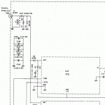
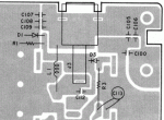
In case you want to take one last shot at fixing the radio I have attached a partial schematic and PC board layout. Notice that the chassis ground symbol (L1 and the antenna jack connect to this) is not the same as the DC common symbol (where R1, D1 etc. are connected). These two ground points are connected together by nine capacitors, C105-C109 plus four others not shown in this piece of the schematic.

Try measuring the DC resistance from chassis ground to DC common. Measuring across C105 will effectively do that. Also measure across C112, D1 and D3. If any of those measurements are near zero Ohms it may indicate a shorted part.

If that doesn't lead anywhere, you can probably find the same radio cheap on Ebay (or its twin the Uniden BC560XLT).
 

Attachments

  • PRO2025schem.gif
    PRO2025schem.gif
    28.6 KB · Views: 1,704
  • PRO2025pc.gif
    PRO2025pc.gif
    39.4 KB · Views: 1,078
Last edited:

Mike_G_D

Member
Joined
Dec 19, 2002
Messages
1,241
Location
Vista, CA
receiver problem

That partial schematic that pro92b provided gives good clues. And I completely second his advice! I would only add that when you check the diodes (D1 and D3) with your ohmmeter that you should swap the leads - you should see higher resistance with one polarity versus the other. If you see near zero ohms in both cases then it might mean a bad diode but the problem is other components are in parallel with it which will affect that result so we cannot be sure.

In any case, what pro92b said about the chassis versus the DC common ground could be extremely important depending on the overall design. If those two are shorted together by some component failure or something (a possible unintentional solder blob say when you were desoldering the antenna connector?) then, again, depending on the design, this could indeed be causing the problem you are seeing!! And this could be an easy fix once you locate the source. I would suspect that static or some strong surge or extremely high RF (say from a nearby transmitter) would most likely blow one of the diodes. But shorted caps are not uncommon as well. If it's a bad cap, you could probably get away with just removing it completely (cut the leads or remove if surface mount) and not bother replacing it, at least initially, and the operation may seem back to normal. You could also do this with a shorted/blown diode but I would not leave it without a replacement for too long as the diodes provide some protection to the sensitive RF front end components - the diodes are designed to give up their lives, as it were, to protect the subsequent components.

Good luck! In any case, I would say you got your money's worth out of that radio but I understand how hard it is to "give up an old friend"!

-Mike
 

mancow

Member
Database Admin
Joined
Feb 19, 2003
Messages
6,880
Location
N.E. Kansas
I would try connecting that coax center to C3 where it leads to that UHF module. That would bypass all the antenna matching circuitry and apply the signal right to the receiver modules. Try that and see if it improves.
 

Mike_G_D

Member
Joined
Dec 19, 2002
Messages
1,241
Location
Vista, CA
receiver problem meets the wolfman

Hmmm...something else I just noticed...when I look at your posted pictures it looks like you are connecting the antenna coax to the radio directly without using the antenna connector. Is this your standard setup now? Or is this how you are evaluating the receiver performance? I ask because using that jumper cable with banana plug and alligator clip as the ground for the coax and clipping the cable to the coax at the spot you show ARE NOT GOOD IDEAS!!!!!!!!!!! You REALLY NEED to have the coax shield attached to its proper grounding point right as close as possible to the the point where the center conductor attaches. This is EXTREMELY IMPORTANT!!!!! I cannot stress this enough!! The way you are using it now I am not at all surprised that you will get odd results!! Again RF acts VERY differently to DC!! That jumper cable attached where it is acts like a tuned circuit with some unknown characteristics doing lord knows what to your receiver performance!! PLEASE - ditch that jumper and replace the antenna connector if possible and use that as it was originally intended!! If you cannot do this (say because you lost or broke the original connector) then you need to pay close attention to how you solder the coax to the circuit board. You need to solder the center conductor right to the correct point with as little exposed wire as possible and solder the shield right to the correct point, ideally right at the ground point at the grounded end of the inductor, L1; you could use an Xacto knife to scrape away some of the PCB coating to reveal the ground underneath if necessary. This may not be easy but it IS VERY IMPORTANT!! DO NOT try and solder the shield to the ground point by using even a short thin wire - that will again just be another component at RF. The shield needs to be directly soldered to the correct point. What you have now will almost certainly screw up your receiver's performance and provides a very poor way to evaluate it to find any further problems if any! In other words, you could be creating the problem with the method you are using to test it!

Sorry - I should have paid attention more to those pictures and asked further questions! It just may be that your receiver is fine - you are just not feeding it correctly at the antenna port!! In any case, we need to fix this before we go any further!!

-Mike
 

pro92b

Mutated Member
Premium Subscriber
Joined
Jun 27, 2002
Messages
1,910
I don't see C3 - maybe you mean D3. That would be a bad idea as it puts DC voltage from the radio into the antenna. Some antennas are DC grounded so it could cause a short circuit that would burn out coils on the UHF board. The front end components are there for protection more than filtering and they should not be bypassed.

I would try connecting that coax center to C3 where it leads to that UHF module. That would bypass all the antenna matching circuitry and apply the signal right to the receiver modules. Try that and see if it improves.
 

Mike_G_D

Member
Joined
Dec 19, 2002
Messages
1,241
Location
Vista, CA
receiver problem versus Godzilla

mancow,

That's also a good idea - but I would still like to clean that antenna connection up before we go further! If he is truly evaluating his receiver performance with his coax attached in that fashion using a jumper cable to provide shield ground connection and using a tapping point that far away from the center conductor termination then he is just asking for problems!! I am just cringing at the thought of how those poor RF waves are getting contorted when meeting that impedance monster!! Maybe low band might not be too badly affected but pretty much anything higher up - EEEGAAADSS!!!!!

Let's fix this and see what we get. If we still have a problem, then I think your suggestion would be a good next step!!

-Mike
 

mancow

Member
Database Admin
Joined
Feb 19, 2003
Messages
6,880
Location
N.E. Kansas
I corrected it to D3.

Yea, I wouldn't want to leave it there permanently or anything but I tend to doubt it would burn anything up. At most it should be a few volts on that line and it should handle it fine for a brief test. Or, he could connect it through a .1 cap just to be sure.
 

Mike_G_D

Member
Joined
Dec 19, 2002
Messages
1,241
Location
Vista, CA
receiver problem versus the Aztec Mummy

pro92b and mancow,

Whew! Between us all we'll get his old girl back on her feet! Anyway, yeah - what pro92b said though I concur with mancow in that a short time testing without the diode protection should be ok (assuming you don't try to do it during a thunderstorm or while some strong RF is present right nearby).

Anyway, I still really want to get rid of that random tuned circuit he seems to be using as his antenna port connection!

-Mike
 
Status
Not open for further replies.
Top