Pro-2006: Unknown Pro-2006 mods

Status
Not open for further replies.
Joined
Oct 9, 2017
Messages
52
Location
Whitehall, Mi
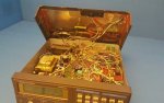
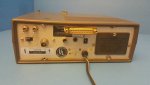
Just received my Realistic Pro-2006 from ebay. I think I may have paid a little much for having the battery beep issue and not knowing what the mods are and if they're working.

However, the system is decked out with the mods and I was told the scanner is working and appears to be though I haven't connect to a better antenna yet.

Here is the eBay link: Realistic Pro-2006 400 Channel WX Fire Police Hyperscan Scanner works | eBay

You can select the right arrow for more images of the case open.

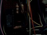
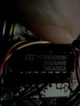
I've attached two images of the chips I found inside if that help with identifying the mods.

Any help would be greatly appreciated as I am most interested in how to connect to the computer using the DB25 serial connector in the back.
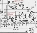
 

Attachments

  • IMG940.jpg
    IMG940.jpg
    37.4 KB · Views: 1,350
  • IMG942.jpg
    IMG942.jpg
    40 KB · Views: 1,346

byndhlptom

Member
Joined
Nov 1, 2005
Messages
399
Location
JoCo, KS (SoDak native)
Pro 2006

Most mods to these scanner mods were documented in Bill Cheek's scanner modification books (1, 2 , & 3). They are often available on line. An interesting read even if you don't plan on doing the mods....

$.02
 

ka3jjz

Wiki Admin Emeritus
Joined
Jul 22, 2002
Messages
25,388
Location
Bowie, Md.
There was a proprietary board that was produced - I'm pretty sure it was called the HB-232; there was a DOS program that went along with it (did Probe work with it? I don't remember, it's been too long)

GL trying to find that board as it's likely as rare as whale shark's teeth, and pretty costly to boot if you do. And since the program ran in DOS, newer versions of Windows won't work with it very well, if at all.

Mike
 

Ubbe

Member
Joined
Sep 8, 2006
Messages
9,033
Location
Stockholm, Sweden
As the listing has ended there's no pictures to look at.
The CE/HB-232 was nothing like the Probe program and OS456 interface.
It was only a serial interface to program the memory and remotly push the buttons.
The Probe/OS456 where interfacing directly to the RF circuit and made it a super fast scanner.

The ICs in you pictures are for analog comparing (signal strenght meter?) and digital interfacing 5v to 12v levels (RS-232?)

/Ubbe
 
Joined
Oct 9, 2017
Messages
52
Location
Whitehall, Mi
Unknown PRO-2006 mods

If you click on the image for the ended item and scroll down you will find the original listing still where you can do what I described to find the photos. I can upload if needed though am not sure on limits of number of files as I recall reading. At least in Google Chrome I can find the listing and I'm not logged into eBay.

I do not notice any meter LED's unless somehow integrated with the Display.

The display has the "Light" switch.

There are two additional toggle switches on the back of the case wired together like STSP (I'm not sure if this is correct or for an additional option).

There is a DB25 (I think at least so may be RS232) female plug on the back of the case. There is s blue trim pot on the top of the case cover.

There is a 12 PIN IC socket on the top of the case cover.

Taped on the cover in a antistatic bag is a chip and the bag is labeled "RAM."

There is additional metal and copper lining the inside of the case cover soldered at the corners.

Three wires coming off the I think Voltage regulator transistor.

The boards are on wafer board like they are custom made and not purchased... then again maybe production wafer kind of dead bug style.

Do you have or know of any references to the DOS applications?

I was thinking interfacing with the computer for DSD+ and maybe even using like a frequency counter.
 
Joined
Oct 9, 2017
Messages
52
Location
Whitehall, Mi
Unknown PRO-2006 mods

Interesting, I've only read Scanners and Secret Frequencies. I'll look into Interlibrary loans and other sources for Bill Cheeks books as well as online.

That is what pointed me to this scanner and I wanted something heterodyne (I have a KTR-1665 labeled "Playback" I also want to restore and mod) and more easilier repaired/mod to refresh my soldering skills than the RTL-SDR systems I've been playing and detecting for radio direction finding and static, noise, interference and jamming with along with microphones the Mini-3 Bat Detector. The Cuban issue has me even more pumped.

I'm not sure with interfacing with SDR#, Radio-Sky Spectrograph and WXTrack yet other than sound card input with scanner discriminator output and maybe sound? For the later two apps I may need to mix the signal for the higher frequencies than 1.3Ghz though I am wondering about needing a microscope also to trim the traces more calculated for the RF Engineered circuit since they do not behave like breadboard designs. Maybe even machined instead of eched too for more accuracy? A broader range would be awesome as I was thinking filling the gaps of the Playback radio to. Probably easier to go lower than higher frequencies from what I read.
 

Attachments

  • s-l1600_inside_case_n_cover.jpg
    s-l1600_inside_case_n_cover.jpg
    35.3 KB · Views: 1,176
  • s-l1600_back_case.jpg
    s-l1600_back_case.jpg
    20.5 KB · Views: 1,327

Ubbe

Member
Joined
Sep 8, 2006
Messages
9,033
Location
Stockholm, Sweden
That connector on top are probably for a display or LEDs to indicate signal strenght, audio modulation and frequency offset +/- Too bad you didn't get those indicators, if they are not to be found in a plastic bag in the scanner. Switches on the back are probably for memory bank switching and/or turbo speed scanning.

/Ubbe
 
Joined
Oct 9, 2017
Messages
52
Location
Whitehall, Mi
Unknown PRO-2006 mods

Yeah, those indicators sound great. Interesting using an IC socket for those connections.

I guess there are plugs like IC's maybe that are similar to an IDE style connector going to a breadboard though used the other way around or you just use the breadboard wire tips as I see there are male and female connections using that design used.

I need to read more of the txt files and references in magazine and websites I've found online. I haven't visited the .dk modification site yet.

I also just opened up the battery compartment and found no battery. Maybe that is why the battery indicator is flashing and beeping. Duh! :) Interesting as I see all the recommendation for the beep are kind of not the best modifications. I saw on radioreference somewhere "IC5 (PC324C, looks like an NEC part) is what needs to be replaced," There is thread that notes a "LM224, but a LM324 would work as a replacement."

I'll read up more on the IC's on the mod boards inside and see what they do and also try to find the modifications you are referring to.

Thanks everyone. Any advise and/or references especially found not in the BIll Cheek's books are greatly appreciated.
 
Joined
Oct 9, 2017
Messages
52
Location
Whitehall, Mi
Charged the 9V battery up, installed and still the battery beep and indicator flashing. OK, the IC change is the next mission.

I found in Michigan I can get "The Ultimate Scanner" and "Scanner Modification Handbook, 1" through mel.org. I ordered and am eagerly awaiting. Now, to see if I can find the other 2 books online at a reasonable price.

Maybe I'll donate to the library also afterwards (making copies and e-scans documents of what I do). Thanks to others reminding me how they forget what they did! :-|)
 

wtp

Member
Joined
Apr 3, 2008
Messages
5,989
Location
Port Charlotte FL
charged up ?

if i remember a rechargeable 9 volt battery puts out 8 volts when charged and even used to say not to be used in certain applications. although it has been some time since i looked into 9 volt rechargeables.
 

pro92b

Mutated Member
Premium Subscriber
Joined
Jun 27, 2002
Messages
1,910
A 9V style rechargeable battery such as the Duracell DC1604 is rated at 8.4 volts nominal with an operating range of 7 volts to 9.5 Volts.

The battery detector in the PRO-2006 has a nominal threshold of 4.6 volts with a tolerance of about 20%. Any 9V style battery, rechargeable or not, should work correctly with the PRO-2006 battery detector.

Before going through all the work of removing and replacing IC5, measure a few voltages as indicated in the attached schematic. The problem might be as simple as a broken wire from the 9V battery connector.
 

Attachments

  • BatteryBeep.jpg
    BatteryBeep.jpg
    100.3 KB · Views: 1,114
Joined
Oct 9, 2017
Messages
52
Location
Whitehall, Mi
I was wondering the charging and quality also. I charged the batter prior and was thinking about what I used the other battery for (came in a two pack with charger I picked up when purchasing some LiFePO4 AA batteries from overseas where I rig a bent piece of household wire in one place say in a two battery requirement device). The 3.4V AA rechargeable batteries work well.

Now, after typing halfway through this I figured I'd better check the 9V 600mAh claim. 0V, nothing. I'll test after charging and see what happens. This battery sat and was not used.

I found the other 9V is in a UYIGAO UA6013L Capacitance Test and seems to be working OK. A 47uF cap measured 52.8uF which isn't that off or the capacitor is wrong. LCD works also for the screen. Thanks for the reminder. The 9V that tested 0V is in the charger and I suspect is bad since shouldn't be discharged to zero though maybe that notes something in the scanner also?
 
Joined
Oct 9, 2017
Messages
52
Location
Whitehall, Mi
I have a moderator post lag time. Thanks for the schematics details pro92b. I'll check that also. I was wondering what would cause a discharge of the battery prematurely and to zero also? Maybe something with the memory module.

I did order the Scanner Modification book 2 (ebay) and 3 (amazon) last night.
 

pro92b

Mutated Member
Premium Subscriber
Joined
Jun 27, 2002
Messages
1,910
IC9 has been known to fail in some cases. If it does regulate to a 5 volt output, it probably is good. Most digital meters can measure DC voltage and current so you can check the current drain from the battery. The 9V battery connector makes this current measurement convenient.
 
Joined
Oct 9, 2017
Messages
52
Location
Whitehall, Mi
I charged the battery. Double checked was 8.6V and placed in the pro-2006 and now there is not a beep or flashing batt indicated. I'll see if the battery discharges overnight if that is the issue.
 
Joined
Oct 9, 2017
Messages
52
Location
Whitehall, Mi
Interestingly, no beep and blinking batt. Battery is at 7.16V. I'm thinking a 9V LiIon charger for the battery might not be a bad circuit to include with the scanner or at least have with velco'd to the scanner and removing the internal 120V to 12V power supply.

I like the idea I read online by kd6ecz (https://forums.radioreference.com/radio-shack-scanners/129242-pro-2006-power-supply-issues.html) of using a "wall wart" power supply for less noise and thinking that will free up room.

The largest RF Shielding cover is soldered on in two points with a ground wire connected. The smaller two RF Shielding areas are not soldered however.

I'm guessing the IC9 is under the larger RF Shield, is that correct? I can only find CN8 test point 1 which doesn't measure anything though the red wire opposite to test point 1 measures 15.5V when plugged in and 6.2V when unplugged.

I see IC5 though I am guessing the Resistors R230 through R233 are under the RF Shield? I can only measure on the IC5 pinouts itself for now. Pin 9 is 1.5V, 8 and 10 are 0V.

The M74HC4050B I noticed on the perforated board has tape with markings with arrows going in and out of the IC for each labeled letters L, M, K, I, J and two pins to a ground symbol.
 

RFI-EMI-GUY

Member
Joined
Dec 22, 2013
Messages
6,868
I wonder if this scanner is from Bill Cheek's personal collection. Last year there was an auction for a ton of scanners that belonged to him.
 
Joined
Oct 9, 2017
Messages
52
Location
Whitehall, Mi
I'm looking forward to the books to study and compare. Would be nice if the software is with the books or at least the code. I really wanted to connect to the computer.

Until I read some more and am comfortable with what is what on the PRO-2006 (found service and owners manuals to read) I am going to focus back on antenna design work and construction.

I see I am going to have to drill out the telescoping antenna hole since all my telescoping antennas are a slightly larger diameter.

I don't have much for antennas where I am working offsite.

I'm feeling the urge for a house wire discone antenna idea I found also online and forgot to save where someone uses a power drill to straighten out and then twist two wires together for the ground plane disk and cone elements. Then the monopole top I was thinking as typical though maybe trying a fractal cover over like in this video: https://www.youtube.com/watch?v=QWd0nEXFnrE using conductive paint and a stencil like this video though I am thinking a more linear/square pattern and not triangular: https://www.youtube.com/watch?v=AX95oaQAjTM

Wondering if I can take some "D" cell battery carbon rods, blend in a blender maybe add some silver/copper powder or just use with the laquer. I wonder what the best binder polymer would be? Nitrocellulose laquer I've read for the metal plating though poly seems would be more UV resistant. I was thinking originally I can use UV resistant Krylon and dust over with the graphite/carbon power then coat again.

Wondering how the noodle foam at Walmart performs? Have to find out what that material is next.
 
Joined
Oct 9, 2017
Messages
52
Location
Whitehall, Mi
Neat, the pool noodles are closed cell polyethylene foam so I am thinking should work great for radio projects other than the potential dyes or maybe other materials affects.. Might be even some toy or residential insulation options too though reads like residential stuff is more dense.
 
Status
Not open for further replies.
Top