Following the approach proposed by MT magazine about the construction of the X-Wing for satcom, I have tried to reproduce it in the variant of a reflective surface made of aluminum with 8 10 and 8 mm and the line of descent in the cable TV directly soldered elements under the Scheme. Today I finished the job and as you can see from the photos is the antenna on the roof due to the listening tests, the results we will feel afterwards.

You are using an out of date browser. It may not display this or other websites correctly.
You should upgrade or use an alternative browser.
You should upgrade or use an alternative browser.
My x-wing
- Thread starter red-dog
- Start date
- Status
- Not open for further replies.

my x-wing
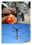
Following the approach proposed by MT magazine about the construction of the X-Wing for satcom, I have tried to reproduce it in the variant of a reflective surface made of aluminum with 8 10 and 8 mm and the line of descent in the cable TV directly soldered elements under the Scheme. Today I finished the job and as you can see from the photos is the antenna on the roof due to the listening tests, the results we will feel afterwards.
Following the approach proposed by MT magazine about the construction of the X-Wing for satcom, I have tried to reproduce it in the variant of a reflective surface made of aluminum with 8 10 and 8 mm and the line of descent in the cable TV directly soldered elements under the Scheme. Today I finished the job and as you can see from the photos is the antenna on the roof due to the listening tests, the results we will feel afterwards.
Attachments
Fast1eddie
Member
Nice! I am looking forward to your further evaluation and report. I am going to build one, gotta get the material together.
For now, my station is a Icom discone into maybe 20 feet of RG-8. Station is at roof level and able to manage the short cable run. Using R7000 and have experienced moderate success so far.
For now, my station is a Icom discone into maybe 20 feet of RG-8. Station is at roof level and able to manage the short cable run. Using R7000 and have experienced moderate success so far.
Looks like you've soldered the coaxial cables directly to the elements...
Are you using RG-6? Can you give us some details of the phasing harness, etc.
Personally I wouldn't have painted it until I knew it worked")
Grazie.
Are you using RG-6? Can you give us some details of the phasing harness, etc.
Personally I wouldn't have painted it until I knew it worked
Grazie.
Wow..that looks great! I like the fact that you used aluminum rods for the reflector instead of wire mesh. How did you come up with the spacing for the reflector elements. The original MT instructions say to use wire mesh with holes not larger than 1''. Let us know how it works!
Hello, it seems that this antenna works. Certainly it is not up to my 2x6 elements, I noticed that focuses on satellite it assumes a certain directivity, albeit limited. As for cable, satellite TV cables are simple with copper braid and foil shielding allluminium with 0.81 speed factor thus reflect the measurements of the lines given by the coupling project MT MAGAZINE.
K5MPH
Member
Do you have an Link for the MT Magazine plans......Following the approach proposed by MT magazine about the construction of the X-Wing for satcom, I have tried to reproduce it in the variant of a reflective surface made of aluminum with 8 10 and 8 mm and the line of descent in the cable TV directly soldered elements under the Scheme. Today I finished the job and as you can see from the photos is the antenna on the roof due to the listening tests, the results we will feel afterwards.
prcguy
Member
Congratulations red-dog, looks very nice! The radials are probably fine for a reflector and I would connect them all together electrically inside the pipe. If you did not use the chassis mount F connectors in the article, the phasing harness should be ok if the overall coax lengths include the length of the chassis connectors. If both harness cables are a little long but by the exact same amount it will be fine but if one cable is off by 1cm it will degrade performance.
The phasing harness in the article is a compromise to provide a 90deg phase shift between dipoles and to help match the roughly 70 ohm dipole elements to 50 ohm coax. Usually this type of phasing harness matches 50 ohm coax to two 50 ohm dipoles and the harness length was adjusted to get the best match while keeping a good 90 deg shift. The dipoles in this project sit about 1/2 wavelength above the reflector to get the desired pattern where most other X-wing types are about 1/4 wavelength above the reflector like a conventional Yagi and are closer to 50 ohms.
This antenna has an omni-directional main lobe that points upward at roughly 45 deg with a null straight up and has a good working elevation of around 20 to 60 deg upward. It was designed for optimum reception of UHF milsats that cover the US, but it should also be good for most of EU. See post # 11 here for the instructions. http://forums.radioreference.com/sa...8-mt-magazine-uhf-satcom-antenna-project.html
prcguy
Do you have an Link for the MT Magazine plans......
Last edited:
Hi
Here in EU 99% of the Time you will hear Satcom Pirates from East Europe. I would say from Romania?
Here in EU 99% of the Time you will hear Satcom Pirates from East Europe. I would say from Romania?
K5MPH
Member
Thanks for the info prcguy,would you happen to know what MT issue and year it was in.....
prcguy
Member
I believe the first part was in the March, 2010 issue and the 2nd part was in May. The project posted here is the raw version before editing by MT to avoid any copyright problems.
prcguy
prcguy
Thanks for the info prcguy,would you happen to know what MT issue and year it was in.....
rbm
Member
Back in 2014 I did some testing on my ST2 antennas to see just how directional they are.
Part of my testing was done on SatCom frequencies.
While doing that, I decided to compare them to my X-Wing antenna.
In the images below, you'll see that on each of two ST2 antennas pointed East and West (on the side of a mast), some of the signals were just barely noticeable at all.
(If you only depended on one of those antennas, in only one direction, you wouldn't even know the other signals existed.)
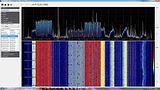
On the X-Wing, they were all there and strong.
Very nice performance!
Both screen captures were within just a few minutes of each other.
There's a little more info in my older post here:
http://forums.radioreference.com/sc...300420-st-2-antenna-question.html#post2273513
Rich
Two ST2 antennas, pointed East and West, simultaneously using two instances of SDRSharp.
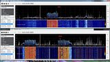
And on my X-Wing:
.
Part of my testing was done on SatCom frequencies.
While doing that, I decided to compare them to my X-Wing antenna.
In the images below, you'll see that on each of two ST2 antennas pointed East and West (on the side of a mast), some of the signals were just barely noticeable at all.
(If you only depended on one of those antennas, in only one direction, you wouldn't even know the other signals existed.)
On the X-Wing, they were all there and strong.
Very nice performance!
Both screen captures were within just a few minutes of each other.
There's a little more info in my older post here:
http://forums.radioreference.com/sc...300420-st-2-antenna-question.html#post2273513
Rich
Two ST2 antennas, pointed East and West, simultaneously using two instances of SDRSharp.

And on my X-Wing:
.
Last edited:
prcguy
Member
In my testing for the article I compared the MT X-wing to a $7,000+ Trivec-Avant AV2090-10 magnetic mount X-wing and my MT version was better. This is partially due to the Trivec-Avant having a pattern that points straight up and there are no UHF satellites straight up in the US. The MT version is optimized for a more realistic 20 to 60deg angle upward and there is no spot in the US where the satellites are any higher than 60deg.
prcguy
prcguy
Back in 2014 I did some testing on my ST2 antennas to see just how directional they are.
Part of my testing was done on SatCom frequencies.
While doing that, I decided to compare them to my X-Wing antenna.
In the images below, you'll see that on each of two ST2 antennas pointed East and West (on the side of a mast), some of the signals were just barely noticeable at all.
(If you only depended on one of those antennas, in only one direction, you wouldn't even know the other signals existed.)
On the X-Wing, they were all there and strong.
Very nice performance!
Both screen captures were within just a few minutes of each other.
There's a little more info in my older post here:
http://forums.radioreference.com/sc...300420-st-2-antenna-question.html#post2273513
Rich
Two ST2 antennas, pointed East and West, simultaneously using two instances of SDRSharp.
And on my X-Wing:
.
@rbm
WTF! You can be happy that you are life in an Country/ Area where the use an Language you understand.
Here everything is in any language than English...
WTF! You can be happy that you are life in an Country/ Area where the use an Language you understand.
Here everything is in any language than English...
- Status
- Not open for further replies.
Similar threads
- Locked
- Replies
- 19
- Views
- 10K
- Locked
- Replies
- 2
- Views
- 3K