Question regarding J-POLE feedpoint

Status
Not open for further replies.

conve36

Member
Joined
May 5, 2008
Messages
161
Location
Menifee/Lake Elsinore, Ca
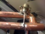
As in the picture below, my question is; (measurments not exact, just example)

If I am to attach the PL-259 chassis mount at say 1.5inches from the grounding point, where do i stop measuring? The middle of the chassis mount or the closest end of the chassis mount to the grounding point?

This is a hard question to "word" so I hope someone understands what I mean...
 

Attachments

  • IMG_0094.jpg
    IMG_0094.jpg
    46 KB · Views: 1,436

mrweather

Member
Joined
Dec 19, 2002
Messages
1,256
I don't think it is all that critical. Have you made any measurements to ensure where you have the mount positioned gives you the best SWR?

On the j-poles I've made I strip the braid from the centre conductor of the coax and attach them to each j-pole leg using stainless steel hose (worm) clamps.
 

SCPD

QRT
Joined
Feb 24, 2001
Messages
0
Location
Virginia
J-pole

On the j-poles I've made I strip the braid from the centre conductor of the coax and attach them to each j-pole leg using stainless steel hose (worm) clamps.

I agree with mrweather. Skip the SO-239 connector, and clamp the center and shield directly to the copper cactus. This way, you can move the feedpoint up and down a bit to get the best match.
 

nanZor

Active Member
Joined
May 28, 2009
Messages
2,807
The measurements are usually from the center of the tee.

Um, I'll be a smart-aleck and hope you aren't trying to use that piece of coax in the pic. :)

At any rate, be sure you do something about common-mode ground currents with either ferrite RF-chokes good up to VHF a few inches down the feedpoint cable, or at least use a few loops of coax (I don't know the magic for coaxial-loop chokes, ie 4-inches, 4 turns, --- 5 inches, 5 turns etc -- you may want to look that up for the band of interest). Note that I've never seen ferrite chokes good beyond 200-300 mhz so ferrite chokes for a UHF version may be hard to find.

Then tune it.

This link may prove useful if you go at least half-way down the long page about the effects of common-mode currents changing patterns as compared to antennas modeled without any feedline attached:

End-fed vertical j-pole and horizontal zepp I-max 2000 vertical

Many antennas are actually looking pretty high upwards, and have their feedline doing the low-angle work poorly - which should really be left to the antenna proper to do. :)

Good luck with your antenna - they are a blast to make - and I've got the cuts and burned thumbs to prove it. :)
 
Last edited by a moderator:

mrweather

Member
Joined
Dec 19, 2002
Messages
1,256
I can think of a few:

- easy to build
- DC grounded
- doesn't require a groundplane
 

clawhammer

Member
Joined
Apr 23, 2008
Messages
69
Location
West Central Florida
Best way to determine proper point of attachment is to use an OLD swr bridge (CB) and solder after best swr is attained. not knowing what freq used it's hard to say what to use for xmitter. if you have a gmrs radio you can use it to get close enough to 400mhz to be efficiant enough. could use a grid dip and amp to get enough power to run meter.
 

conve36

Member
Joined
May 5, 2008
Messages
161
Location
Menifee/Lake Elsinore, Ca
I am still confused why some plans I have found on the net have the center conductor of the coax attached to the long element and some plans show it attached to the smaller stub. Someone please tell me why?
 

nanZor

Active Member
Joined
May 28, 2009
Messages
2,807
It will work either way, but with the center conductor connected to the shorter element, the elevation angle will be higher. The meter used to tune it won't know the difference. Perhaps the author didn't know the difference when he attached the center conductor to the short element.

I haven't seen any plans showing the center conductor to the shorter element, except for W8JI's modeling of it to show the higher elevation angle as a comparison.

Unless you need a high elevation angle, stick to attaching the center conductor to the longer element. Choking the feedline is highly desirable.
 
Status
Not open for further replies.
Top