Let's try adjusting things so your SDR# installation is working better and it's more efficient for you too.
- obviously the basics in the settings (the gear icon) should be already resolved: pick a sampling rate you can use, it looks like you might be using 1.4 MHz which is fine, I use 1 MHz myself pretty much constantly. RTL AGC and Tuner AGC off, set the gain to maybe 36.4 dB as a start and adjust it
sparingly as required - when you raise it the noise floor is going to come up along with the signal too. And obviously make sure your ppm is accurate, tune to your local NOAA weather frequency and zoom in the spectrum (top right hand corner control) so it's as centered on frequency as possible after about 15-20 mins.
- click the arrow icon in the Source section on the sidebar - you know which device you're using so no sense wasting space to remind you
- the Bandwidth should be set to about 8000 for almost anything (that's my opinion and I'm sure others have their own ideas on that one) using AM or NFM, WFM will obviously need more bandwidth but that's strictly used by FM radio stations and nothing else that I'm aware of. 8000 is an excellent starting point then you can adjust it
sparingly as required but as noted above, that 2882 amount is not acceptable for anything in my experience
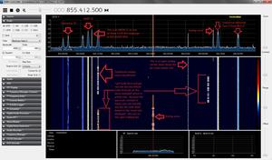
- enable the Snap to grid so you're following the band allocation stepping sizes, in this case the 850 MHz range uses 12.5 kHz stepping so you're on frequency. Having said that, a lot of businesses in the US are now moving to using DMR comm systems which use narrowband spacing of 6.25 kHz, and some NextEdge systems can and do use 3.125 kHz so you might find some digital stuff buried in between the "normal" stuff using 12.5 kHz. It makes tuning easier as well - the frequencies you're tuning in on in those screenshots are not anything that would be in use by entities with actual legal transmission licenses. Having said that, if you find yourself following the stepping of the band you're monitoring is accurate and yet you find a signal of some kind "in between" the allocation stepping, adjust it as necessary but remember that you've adjusted it in case you can't quite nail another frequency directly by tuning from the spectrum using the mouse, etc. I added the 3.125 kHz stepping as well as a 1.25 kHz stepping in my SDR# config file, it's easy to edit by just adding them. I did that because by default it doesn't cover the 3.125 kHz that some NXDN systems are using in my area so it's necessary.
- enable the Correct IQ setting - this will get rid of that center spike that RTL sticks are affected by. Better quality hardware like Airspy, HackRF, SDRPlay, BladeRF, etc, don't have that problem as far as I know. There's no sense seeing a signal spike dead center when there's nothing there and when you're tuning it's generally best to get the tuned frequency centered or close to it - if you note at the fringe edge on the left and right there's an area (noted by how the noise floor line slopes down to the edges of the spectrum) the signal drops considerably, like 5dB compared to the "main" noise floor which is roughly -50dB. You want to avoid trying to tune into anything on the fringe edges because they're most likely just ghost images of other frequencies and when you do attempt to tune them you'll get nothing at all
Because a lot of the other aspects are of a more personal nature like the spectrum and how it visualizes things and most importantly the waterfall which can really be important in determining something from a given signal, these remaining adjustments are just that: personal ones and you have to set it up for you the best way you like. Having said that, here's what I recommend which should make this software work better for you.
- The Zoom function I use sparingly and only when I'm trying to do something specific, the majority of the time I just leave it at the lower setting so the spectrum is "native" and unaltered
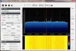
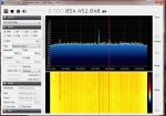
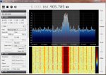
- the Contrast setting is perhaps the biggest and most important one of all. If you were to take a general glance at your screenshots above all that jumps out at you is that huge wall of yellow and that overpowers the idea of having a visual representation of the activity going on. Yes, there's some traces of red in there meaning signals but, to paraphrase an audible term you're "drowning out the signal in the noise" so adjust the contrast to a point where all you are going to visualize are the signals, not the noise. Here's a screenshot of how I set my waterfall just as an example - before I add it note that my Range setting is at a point where my noise floor is at the bottom of the spectrum.
As slicerwizard commented, if you know the noise floor (easy enough to see on the spectrum) there's zero reason to leave the Range setting at a point where half your vertical spectrum is showing you the noise floor - it's no good for anything down there in the noise, that's what the waterfall is for (to pick out signals from the noise). If you adjust your Range so that the noise floor is just barely visible as mine is you can then adjust the Contrast as well because those two settings are quite related. If I adjusted it to the next lower notch I'd only see a few peaks on the display so I keep the noise floor barely visible but that's just me. Anyway, I keep mine looking basically like this constantly:
Now, if I'd had the Range and Contrast up to the same or similar levels as you did in your screenshots, those signals would still be there obviously, I'd still see the peaks on the spectrum where they are but the visual representation of the signals would make it nearly impossible to make out exactly what they happen to be to any degree at all, and certainly the Morse Code 'decoding' by eye would be pretty much impossible for anyone save maybe Data from the Star Trek series/movies.
")
The point being: the whole idea of monitoring is to be able to listen, speaking from the audible sense. Now that we have these kinds of computer related tools for monitoring it's gone from being all audible to audible plus the visual so we can see what we're monitoring at a glance. After a period of time you develop the ability to know exactly what type of transmission (analog, digital and even what types of digital in use like P25, DMR, NXDN, etc) you're seeing at any given moment - that isn't very easy to do when the visual info is being "drowned out" by the noise as represented by the waterfall, once again.
And finally, as slicerwizard noted, bring that volume down to about 40-50% which is more than enough for DSD+ to really work great. DSD+ will show you not only on the info as it's scrolling by whether or not you have a lot of errors but also on the titlebar of the DSD+ window it shows a neat graphical scale of the decoding percentage (how well it's working based on the signal it's getting). If you get a lot of errors it could be caused by:
- excessive volume from SDR# as noted
- incorrect ppm setting (1 or 2 ppm either way can totally wreck a decode in progress - when I use OP25 under Linux even just 1 ppm can totally stop my ability to decode P25 Phase I or II, it's that precise in terms of what it can work with)
- not enough gain on the signal to begin with
All of these and even others are easily fixed but if you're "new" to this way of doing things then sure, there's a learning curve involved and it can be relatively steep for someone that has only used traditional scanners over the years and may not be that experienced with computers either (which may or may not be the case with you, steve-kc7byp, I'm just saying it in general).
Hopefully these tips will help improve your monitoring with SDR# and DSD+. If you don't already own an R820T2 based stick (the improved model with the temperature controlled oscillator upgrade) you might consider getting one. They're fairly cheap nowadays, RTL-SDR.com has some for only $25 and it comes with two antennas which is pretty nice. They are the preferred version of an RTL stick nowadays - I'm still stuck with the old original but very reliable NooElec sticks (I have two) and I hope to skip over newer low end sticks soon and jump straight to either an Airspy or an SDRPlay.
Good luck...
Edit: DOH, in the image I show the NXDN CC at 855.01625, it's actually 855.10625 so, in case nitpickers noticed I don't want to get creamed for it.