T Splitter Attenuating Signal?

Status
Not open for further replies.

Jimbo695

Member
Joined
Jan 19, 2010
Messages
184
Location
Hauppauge NY
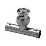
Hi, folks. I'd like to run my SDRPlay off the dipole connected to my HF rig by using a 239 T connector. My concern is that the addition of the connector will attenuate the signal both for the Play and for the rig. Any ideas appreciated. Thanks to all.
 

kb5udf

Member
Premium Subscriber
Joined
Apr 7, 2004
Messages
803
Location
Louisiana
Probably not a good idea

If you ever want to transmit on the HF rig, you can't use a T split, because the SDR would
burn up in short order if not immediately. Yes you could engineer ways around this, but they would not
be worth the effort and expense.

The two most reasonable options I see assuming you transmit on HF:

1 Use a coax switch of reasonable quality to connect the antenna to either sdr or hf rig but not both at same time
2. erect a second r/x antenna for the SDR
 

rbm

Member
Joined
Jan 25, 2005
Messages
1,395
Location
Upstate New York
Here are some 'Ball park' losses for splitters:
(per port)

A 2-way splitter has around 4 dB loss
A 3-way splitter has around 7-8 dB loss
A 4-way splitter has around 9-11 dB loss
An 8-way splitter has around 13.5 dB loss

rbm
 

Jimbo695

Member
Joined
Jan 19, 2010
Messages
184
Location
Hauppauge NY
Thanks everyone. Think maybe I'll just disconnect the antenna from the rig each time I want to hook up the Play.
 

M105

Member
Joined
Sep 13, 2005
Messages
399
Splitters are a bit misunderstood. Yes, a two way splitter can deliver about half the input power (-3.5db) to the output ports. But here is the thing, power = voltage x current and the splitter is a transformer. The receiver represents a load. The receiver load may only be 10% of the available power. Just to use round numbers and arbitrary units lets say we have 10mw of available signal power. We have two receivers that each present a 1mw load. If we split the 10mw signal there is still 5mw of power available on each output port. Since our receivers only pull 1mw load then each still has all the signal it needs. The signal level on each receiver doesn't noticeably change. So in this case the splitter causes no problem.
-
In other words, if you have enough input signal power it can be split with no ill effects. But if you don't then you will notice the attenuation. If you are listening to a weak signal that say has only 1.5mw of power and you split it in the example above, each receiver will only get .75mw. Now your S meter will suffer and your ears will strain since the signal to noise ratio just took a dive.
-
Lesson here is that strong signals can be split but weak signals may need to be amplified BEFORE they are split. Place any amplifier as close to the signal source as possible and ahead of any splitters. It can get more complicated with multiple splitters, different receiver designs, and impedance changes when loads are turned on or off but in general consider a splitter as a power distributor. It may not hurt a thing if your have sufficient signal to begin with. The good news for SDR users is that, at least in the VHF/UHF range, hardware designed for television antenna systems works great and is inexpensive. Trial and error is easy.
-
For the original poster's question. I would use a good coax switch. Hooking a transmitter and receiver together with a splitter is a recipe for disaster!
 
Last edited:

popnokick

Member
Premium Subscriber
Joined
Mar 21, 2004
Messages
2,840
Location
Northeast PA
The OP asked about a "T Splitter". I think there may be confusion in this thread regarding coaxial T-connectors (not "splitters") that simply make a 3-way electrical connection, and true coax splitters or splitter-amps that actually have components inline.
I would call this a T-connector (smaller pic on left) and the larger pic is a coax splitter with inline components (capacitors, inductors, and other RF-active components). From an RF perspective they behave very differently and referring to a T-connector or T-coupler as a "splitter" may confuse the issue.
 

Attachments

  • BNC-T coupler.jpg
    BNC-T coupler.jpg
    2.1 KB · Views: 222
  • CATV splitter amp.jpg
    CATV splitter amp.jpg
    24.4 KB · Views: 228

slicerwizard

Member
Joined
Sep 19, 2002
Messages
7,643
Location
Toronto, Ontario
Splitters are a bit misunderstood. Yes, a two way splitter can deliver about half the input power (-3.5db) to the output ports. But here is the thing, power = voltage x current and the splitter is a transformer. The receiver represents a load. The receiver load may only be 10% of the available power. Just to use round numbers and arbitrary units lets say we have 10mw of available signal power. We have two receivers that each present a 1mw load. If we split the 10mw signal there is still 5mw of power available on each output port. Since our receivers only pull 1mw load then each still has all the signal it needs. The signal level on each receiver doesn't noticeably change. So in this case the splitter causes no problem.
So what circuitry is there in the front end of a receiver that makes it draw a constant power? As the voltage (signal strength) increases, the current would have to decrease to maintain the same power draw. Does not compute.
 

M105

Member
Joined
Sep 13, 2005
Messages
399
Automatic Gain Control. As long as the receiver gets enough signal, it will compensate. That's not to say you can't overload the front end but any decently designed receiver will adjust over a wide range. If you have a strong enough signal you can split it without much effect on the receiver. All I am basically saying is that inserting a splitter doesn't automatically cut your receiver performance in half as many seem to preach. In many cases it will have no noticeable effect.
-
A splitter just divides power at a given impedance, if sufficient power is available to the receivers after the split they will perform as well as they did when connected individually before the split. Try it sometime and note the S meter readings.
 
Last edited:

paulears

Member
Joined
Oct 14, 2015
Messages
786
Location
Lowestoft - UK
Why do people never just plug things up and try! The physics above is sound. The advice accurate and sensible, but using a T piece to split one antenna to two receivers works amazingly well. 3 or 4dB is perfectly acceptable if you are not wanting to receive signals on the limits of the receiver's capability. I have in the workshop at the moment an SDR and a scanner connected to a single antenna with a hotchpotch of T pieces adaptors can cables for some testing I was doing, injecting signals from an RF generator to test rejection, and the SDR and scanner continued with all the usual stuff they work on. I turned the gain up on the SDR a smudge, but frankly, losses through all the connections are well within the limits, and I still hear all the stuff I usually listen to, with the exception of a distant marine shore station that only just lifted the squelch, and now it doesn't.

T pieces are cheap enough to have laying around being useful, and are worth trying. In professional comms systems there are all sorts of circulators and sniffers being used, let alone duplexers and filters and all of these things cause signal loss. If the signal is high enough, losing 3dB is quire livable. After all 2dB or less is generally accepted to be difficult to hear, benefits wise.

Do the split and try it out. If it works, use it. Radio is an experimentation hobby and all people do nowadays is hunt for youtube videos that are usually appalling or confusing.

Jimbo says in his first post he'd like to do something, and has the bits. If he uses them there will be loss. The only question should be - is the loss small enough to make the system work? He knows what he should hear, so plug it up and try it out. Do NOT be put off by gloom and doom. After all, if you plug it up and you cannot hear your favourite airfield or whatever, and that is important, you unplug it again. For goodness sake - this is not dangerous, not expensive and it's exactly what you do to improve your own knowledge.

Of course, the physics is important - but you won't learn without trying things.

Sorry for being so grumpy - but this is an excellent practical thing to just try, not prevaricate about. Tell us the results and that will be really helpful for everyone - what were the downsides, and what was good about it? That's genuinely useful info.
 

M105

Member
Joined
Sep 13, 2005
Messages
399
Do the split and try it out. If it works, use it. Radio is an experimentation hobby and all people do nowadays is hunt for youtube videos that are usually appalling or confusing.

Or try sell you something! :)
 

paulears

Member
Joined
Oct 14, 2015
Messages
786
Location
Lowestoft - UK
Why would you blow out the SDR? You could pick up the mic and call CQ, but that comes down to discipline, doesn't it? Still perhaps you could build a little disconnect triggered from the PTT - isolates the SDR input and perhaps sticks a short on it? Nice little project?
 

prcguy

Member
Joined
Jun 30, 2006
Messages
15,344
Location
So Cal - Richardson, TX - Tewksbury, MA
A receiver does not "draw" a constant amount of power. After you whittle down the receivers front end circuit into its simplest form, the front end of a receiver is just a resistor around 50 ohms when calculating how much voltage and current are presented to it from an antenna. If the received voltage goes up then the current goes up proportionally.

The bottom line on splitters or dividers with matched 50 ohm ports is they will loose a constant amount power with weak or strong signal levels. A good two-way divider usually will have less than 3.5dB loss, a good 4-way is usually under 6.5dB loss and so on. Cheap TV splitters have more loss but I've never measured one that's as bad as rmb posted.

A "T" adapter used as a splitter is a different animal and will have a minimum of 3dB loss but it can be much, much worse and will vary with frequency, cable lengths, load, etc because there is nothing to match the ports like in a purpose designed splitter or divider.
prcguy

So what circuitry is there in the front end of a receiver that makes it draw a constant power? As the voltage (signal strength) increases, the current would have to decrease to maintain the same power draw. Does not compute.
 

M105

Member
Joined
Sep 13, 2005
Messages
399
A receiver does not "draw" a constant amount of power. After you whittle down the receivers front end circuit into its simplest form, the front end of a receiver is just a resistor around 50 ohms

Yes! That is a better way to express it. With the SDR I think it is a 75 ohm impedance like a TV receiver.
 
Status
Not open for further replies.
Top