Notch Filters and Effects

Status
Not open for further replies.

tomasG

Member
Joined
Jan 14, 2010
Messages
152
Location
Lancaster, CA
One more thing -- if you're getting interference from a particular frequency you can place a T inline close to the scanner input. Antenna through to the scanner. But on the T side take a piece of RG58, 8, even RG59 or RG6 - and cut it to the 1/4 wave ELECTRICAL wavelength of the frequency that is offending. Because it is tuned to the offending frequency, like a paging transmitter at 152.840 that sucks wind, it will shunt to the stub. You'll get about 35-50dB-ish attenuation at the stub frequency.
 

zz0468

QRT
Banned
Joined
Feb 6, 2007
Messages
6,034
One more thing -- if you're getting interference from a particular frequency you can place a T inline close to the scanner input. Antenna through to the scanner. But on the T side take a piece of RG58, 8, even RG59 or RG6 - and cut it to the 1/4 wave ELECTRICAL wavelength of the frequency that is offending. Because it is tuned to the offending frequency, like a paging transmitter at 152.840 that sucks wind, it will shunt to the stub. You'll get about 35-50dB-ish attenuation at the stub frequency.

This is true, but there is a problem: The Q of a piece of coax will be so low that the notch will end up broad enough to take out most of the entire band, not just the single frequency of interest. If that's what you want, that's fine, but caveat emptor. If you need to notch a single frequency, or more correctly, a very narrow band of frequencies, a cavity notch filter will be required.
 

tomasG

Member
Joined
Jan 14, 2010
Messages
152
Location
Lancaster, CA
Last edited:

zz0468

QRT
Banned
Joined
Feb 6, 2007
Messages
6,034
You are mistaken. You will lose +/- 1MHz. This trick has been used for years. An entire band? Hardly. Here's a primer:

WAMU 88.5 FM American University Radio - Engineering FAQ
PAR Paging Notch Filter VHFTN152-158 Product Reviews

With a little research you'll come to appreciate the solution.

On the contrary, I am not mistaken. I am not disputing the effectiveness of notch filters. I am disputing that making one out of small diameter coax is going to be narrow enough to notch out a single frequency without taking out a huge chunk of the rest of the band. Your links are irrelevant to my comment.

Comparing a commercially designed notch filter such as the PAR filters, with a quarter wave stub made from RG58 is a comparison of apples and bananas. See my post below...
 
Last edited:

zz0468

QRT
Banned
Joined
Feb 6, 2007
Messages
6,034
The screen shot is taken from an HP network analyzer. The center frequency is 160 MHz, and the markers are at 144 MHz and 174 Mhz. The black horizontal line across the center represents zero loss, and the notch was created with a quarter wave open stub made of RG 58. As you can see, loss at the band edges is down about 10 db, with the notch center down about 32 db.

As I stated, a notch filter made from coax will take out the entire band.

Any questions?
 

Attachments

  • SCRN00.JPG
    SCRN00.JPG
    50.5 KB · Views: 4,175
Last edited:

WA1ATA

Member
Joined
Jun 18, 2010
Messages
416
Location
Fairhaven MA / San Jose CA / Kihei HI
ZZ0468 -- if you have some RG6 or RG8 and/or LMR400 around, I'd love to see what that looks like. I assume that the lower loss cables will have sharper nulls.

I experimented a bit at reducing 152MHz pager interference to 160MHz railroad signals, using a BNC T with a BNC to F adaptor with a foot or so of RG6. It did help, even though it also clearly attenuated the desired signal.

I don't have test instruments and progressively trimmed it for maximum notch. Assuming that the plot for RG6 is the similar to RG58, but sharper rolloff, I can see why my best performance was with the notch considerably lower than 152. With maximum attenuation at 152MHz, there was excessive attenuation at 160/161Mhz. With the notch freq below 152MHz, it dropped the pager enough to reduce intermod, but didn't knock off the railroad signal as badly.

It was better than just using a straight wideband attenuator of to reduce intermod.

My real solution was to simply change to a scanner that is less prone to intermod, but I'm curious about what can be done with a 1/4 wave stub with low loss coax.

-------------------------------------------------------

What does the notch look like at 3/4 wavelength? Sharper or less sharp ? For your example, I'm assuming that there will also be a notch up around 460MHz. Correct ?

Would a coax 3 times longer give a better 152MHz notch?
 
Last edited:

zz0468

QRT
Banned
Joined
Feb 6, 2007
Messages
6,034
Oddly, it sure doesn't look like an entire band is gone. 10dB is nothing! One S unit is 6dB. Sheez.

Clearly you don't understand what it is you're looking at. That's 10 db at the band edges. At 20 db down, that's a 10 MHz wide piece of spectrum. That's the the difference between .5 uv and 5 uv. Or 1uv vs. 10 uv,10 MHz wide.

That is NOT acceptable performance, so far as I'm concerned. If you want to compromise your receive performance that badly, I guess that's your business. :roll:
 

zz0468

QRT
Banned
Joined
Feb 6, 2007
Messages
6,034
ZZ0468 -- if you have some RG6 or RG8 and/or LMR400 around, I'd love to see what that looks like. I assume that the lower loss cables will have sharper nulls.

It would probably be slightly better. I'll be happy to run some plots later today, I just don't have the time right now.

I experimented a bit at reducing 152MHz pager interference to 160MHz railroad signals, using a BNC T with a BNC to F adaptor with a foot or so of RG6. It did help, even though it also clearly attenuated the desired signal.

It's probably a fair estimate to say that your railroad signals would be down at least 10 db, while your notch was at 30 db, assuming you nailed the tuning.

I don't have test instruments and progressively trimmed it for maximum notch. Assuming that the plot for RG6 is the similar to RG58, but sharper rolloff, I can see why my best performance was with the notch considerably lower than 152.

Yes. At some point, the notch would reduce the 152 MHz signal to below the 3rd order intercept of the receiver, and the internally produced intermod would stop. I can't say at what point that would happen, but the loss at 162 MHz would obviously be less than 10 db at that point.

Ham band coverage would stink, but that's not an issue for some people.

With maximum attenuation at 152MHz, there was excessive attenuation at 160/161Mhz. With the notch freq below 152MHz, it dropped the pager enough to reduce intermod, but didn't knock off the railroad signal as badly.

Yep. And now you can see why.

What does the notch look like at 3/4 wavelength? Sharper or less sharp ? For your example, I'm assuming that there will also be a notch up around 460MHz. Correct ?

I just ran it. The center of the notch is at 475 MHz, and the skirts are nearly identical, with a 10 MHz wide segment at 20 db down. The only apparent difference is that the notch is not as deep, in this case 28 db.

Would a coax 3 times longer give a better 152MHz notch?

Based on what I just saw, I'd have to say no. Some commercially made cavities are 3/4 wavelength long, and that's done for performance, but in those cases, the coupling loops are optimized, the diameter of the coaxial section is huge in comparison to a piece of RG58 or RG8, and they're using temperature stabilized materials like Invar.

Later, I'll show you some plots using RG6, RG8, and 1/2" heliax. No time right now.
 
Last edited:

WA1ATA

Member
Joined
Jun 18, 2010
Messages
416
Location
Fairhaven MA / San Jose CA / Kihei HI
Your effort is very much appreciated.

zzo468 said:
I just ran it.<sweep at higher freq of same RG58 stub> The center of the notch is at 475 MHz, and the skirts are nearly identical, with a 10 MHz wide segment at 20 db down. The only apparent difference is that the notch is not as deep, in this case 28 db.
That sound's like, on a percentage basis, that it might be a bit sharper. The higher loss of RG58 at 475MHz is most likely the reason for the notch not being as deep. Having a notch up in the 460-485MHz band where a lot of freqs of interest are located is yet another disadvantage of the coaxial stub notch. I note that this thread is 1 scanner, multiple antennas. This problem has shown that there is a lot of value in multiple scanners, each covering one freq band, with an antenna optimized for that frequency.

If the percentage bandwidth is better, then a better 152MHz notch might be a 3/4 wavelength stub .... in other words one that has the first notch at 50.67MHz. Obviously it wouldn't be as good as the ultra-high Q of a cavity, but enough to give me the option of using a full dipole (or the end fed dipole of a J-pole) rather than a rubby ducky, without overloading the front end.

It is more of an intellectual challenge and curiosity that a real problem, since only one of my 3 scanners is strongly affected, so don't feel pressured to do the tests right away.

Thanks,

Charlie
 
Last edited:

zz0468

QRT
Banned
Joined
Feb 6, 2007
Messages
6,034
Ok... some additional plots, submitted without comment:

RG6, with a 32db notch, and 5.6 MHz wide at the 20db points.

RG8 with a 40db notch and 10 MHz wide at the 20db points, and

1/2" Superflex, 43db, and 10 MHz wide at the 20db points.

Remember, Markers 1 and 2 represent 144 MHz to 174 MHz, the entire VHF high band.
 

Attachments

  • RG6.JPG
    RG6.JPG
    52 KB · Views: 3,694
  • rg8.JPG
    rg8.JPG
    55.7 KB · Views: 3,931
  • half inch superflex.JPG
    half inch superflex.JPG
    55.9 KB · Views: 3,516
Last edited:

zz0468

QRT
Banned
Joined
Feb 6, 2007
Messages
6,034
Your effort is very much appreciated.

Not a problem. Any excuse to play with my toys... :p

That sound's like, on a percentage basis, that it might be a bit sharper.

Perhaps, but on any given frequency, as you can see, that doesn't really buy you anything. The only thing that will really improve the situation is higher Q on the stub.

The higher loss of RG58 at 475MHz is most likely the reason for the notch not being as deep.

Absolutely.

Having a notch up in the 460-485MHz band where a lot of freqs of interest are located is yet another disadvantage of the coaxial stub notch.

Yes, and if you open up the frequency span, you'll see that it doesn't end up being a single notch, and the loss on un-notched frequencies is not zero.

I note that this thread is 1 scanner, multiple antennas. This problem has shown that there is a lot of value in multiple scanners, each covering one freq band, with an antenna optimized for that frequency.

Yes, and these notch filters might be useful for increasing the isolation of, say, high band signals being received on a UHF antenna, before the different antennas are combined.

If the percentage bandwidth is better, then a better 152MHz notch might be a 3/4 wavelength stub .... in other words one that has the first notch at 50.67MHz...

I didn't bother uploading the plot, but a 3/4 wave stub made from RG8 ended up with a 32db notch, and 10 MHz wide at the 10db points, and 5 MHz wide at the 20db points. Still a significant hit to performance, but not as bad as the 1/4 wave stub.
 
Last edited:

WA1ATA

Member
Joined
Jun 18, 2010
Messages
416
Location
Fairhaven MA / San Jose CA / Kihei HI
Great data and plots.

As expected, the lower loss cables have higher Q and a deeper notch. And the higher impedance RG6 doesn't have as much attenuation at freqs well away from the notch ..... obvious in hindsight.

The bottom line is that maybe the 1/4 wave stub would work to keep a 15xMHz pager out of an airband receiver, but even then the passband loss is 3-6dB. But the coax stub is not much help in reducing a 152 or 159MHz pager while trying to receiver other VHF Hi freqs or the 2 meter band.
 

tomasG

Member
Joined
Jan 14, 2010
Messages
152
Location
Lancaster, CA
Clearly you don't understand what it is you're looking at. That's 10 db at the band edges. At 20 db down, that's a 10 MHz wide piece of spectrum. That's the the difference between .5 uv and 5 uv. Or 1uv vs. 10 uv,10 MHz wide.

That is NOT acceptable performance, so far as I'm concerned. If you want to compromise your receive performance that badly, I guess that's your business. :roll:

Context. These are scanners.

I offered a suggestion to the OP. Coaxial stub filters are broad! Although the recovery isn't as fast as a PAR filter it is fast enough. A PAR takes 4MHz to recover and still be down 3dB. 20dB isn't that bad and is hardly 1 bar. Its as if you expect to hear a HT at .18uV on a scanner which many have a hard time doing. 20 dB is nothing. A mere scanner is gonna have a heck of a time hearing anything if it has frontend overload that bad already.

I'm listening to a full scale repeater right now that I just attenuated 20dB and its still full scale. Listening to any of the weather channels I can knock each down by 20dB and still have full or near full scale. S9+10dB is 160uV. Take off 20dB and what do you have? Still S8+. S4 is 1.6uV. Should we use 12dB SINAD or 20 for 1uV? If one is playing in the dirt to begin with buy a better receiver and not a scanner.

Context.

An entire band would be 137-174. Or 116-137. I know of no affordable filter than can knock down an offending signal by 35dB and recover 3-6dB within
 

zz0468

QRT
Banned
Joined
Feb 6, 2007
Messages
6,034
I offered a suggestion to the OP. Coaxial stub filters are broad!

Your initial response to my caveat stated that the notch would be +/- 1MHz. The plots indicate otherwise.

20dB isn't that bad and is hardly 1 bar.

20db is the equivalent of reducing a 100 watt transmitter to 1 watt. That's a SEVERE reduction in range.

20 dB is nothing.

At what point does excessive loss become a problem to you? 20db is not "nothing".

An entire band would be 137-174. Or 116-137.

You're reduced to arguing semantics. The plots very clearly define the degree of signal loss one would incur if they decide to use a simple stub. People can now make an informed decision, as opposed to a misinformed decision.
 
Last edited:

tomasG

Member
Joined
Jan 14, 2010
Messages
152
Location
Lancaster, CA
Yes, a complete band is more than 10MHz. VHF public safety is 36MHz wide. You made the statement.

But you win. You're smarter. You know more. 20dB is so insignificant that the attenuator on a Uniden is, wait, here it comes -- 20dB! You were so desperate to show that you know more that you pulled out an analyzer and started cutting stubs to prove it. If you take 20dB off of a 1 watt signal (which is what, -30dBm compared to a 100 watt transmitter at -10dBm?) 20dB IS a lot. Tell ya what -- give Dale at PAR Electronics a call and talk real world. Maybe even talk about adding a 10dB preamp AFTER the stub to recover some of the loss without the interference. For the record there is little between 152-153 worth listening to.

CONTEXT. PERSPECTIVE.

I will stick with my statement of +/- 1MHz because the recovery is fast enough. As I pointed out even the PAR spreads out +/-2MHz on both sides until it's only down 6dB. 6dB is one S unit and attempting to compare a 100 watt transmitter to a one watt transmitter doesn't fly. For a 100 watt transmitter to sound twice as loud you need 800 watts. These are scanners that as soon as one adds an external antenna to them they frontend overload and the mixer goes whacky and they create their own crap anyway.

Use a stub or don't use a stub. But please lose the attitude directed at me. You do not need to find anything I post and offer opposition, which is exactly what you've done. If you're playing down in the dirt and expect a stub to get rid of an offending kW paging transmitter it isn't going to happen.

I am listening to weather at 162.500 and its reported RSSI (on Uniden's scale that means little in the real world) and it is at 167-175. If I add 20dB attenuation I drop RSSI to only -- what? No noticable effect? Don't that beat all. NOAA transmitting at 100 watts and received full scale is still full scale after knocking it down 20dB? Wow. I never saw that coming.

OK. Let's take a not so solid signal. North Hollywood Sheriff. Full scale and a RSSI of 155. Add 20dB of attenuation and it drops to 136 with a bit of white noise. I'll bet if someone really, really, really wanted to her No. Hollywood LASD but couldn't because of a damn paging transmitter causing interference (scanner created frontend overload non-linear mixer intermod) from 21MHz away the stub would be wonderful. A little white noise and I can hear them; no stub and I can't hear them. But see this is a bad example because I attenuated LASD ON FREQUENCY and not the paging transmitter 21MHz away.

CONTEXT. PERSCPECTIVE.

Perhaps instead of looking for disagreement perhaps we could focus on the mutally agreed fact that a stub can and does work. Let the user decide what is acceptable to THEM and THEIR scanner. Quit freakin' nit-picking.
 
Joined
May 11, 2011
Messages
23
Location
Encino, CA
Thank you for the stub trick. It worked great! But I am little concerned being new here that it looks like certain roosters rule the house. A lot of work went into proving you wrong and as it turned out my results were pretty good. Is it always like this here? ZZ, dude. Take a chill pill. I read a bunch of your posts and I must say that it appears that there is only one correct answers. Yours. And I thought QRZ was a rough part of town.
 

zz0468

QRT
Banned
Joined
Feb 6, 2007
Messages
6,034
I almost decided not to dignify this with a reply, but there are some egregious flaws in your thinking that I can't, in good conscience, allow to be propagated to people who are here to learn.

20dB is so insignificant that the attenuator on a Uniden is, wait, here it comes -- 20dB!

That value was chosen because it IS a significant value, sufficient to eliminate front end overload under most typical circumstances.

You were so desperate to show that you know more that you pulled out an analyzer and started cutting stubs to prove it.

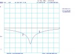
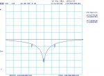
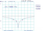
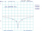
The network analyzer lives on my work bench about 18" from my computer. It gets used almost daily. It's a pretty cool toy, and it's not desperation that causes me to turn it on. Besides, a picture is worth a thousand words, and a real sweep of a real stub made of real coax is pertinent to this discussion.

Maybe even talk about adding a 10dB preamp AFTER the stub to recover some of the loss without the interference.

This statement reflects a profound lack of understanding how receive systems work, and is the main reason I chose to reply at all. I would suggest reading up about noise figure, and how loss and degradation in front of the first active device in a receiver is lost forever and CANNOT be recovered.

I will stick with my statement of +/- 1MHz because the recovery is fast enough.

In spite of the fact that the plots above indicate otherwise? Suit yourself.

Oh, and BTW, the proper term for it is "roll off", not "recovery".

As I pointed out even the PAR spreads out +/-2MHz on both sides until it's only down 6dB.

But my comments relate to coaxial stubs. Why do you keep bringing up PAR filters?

6dB is one S unit and attempting to compare a 100 watt transmitter to a one watt transmitter doesn't fly.

The comparison DOES fly when you're discussing 20db losses.

For a 100 watt transmitter to sound twice as loud you need 800 watts.

Huh? That's a 9db difference. In FM systems, "loudness" of a transmitter is determined by deviation.

But please lose the attitude directed at me.

I only pointed out that while your original post about the stub was correct, the response of the stub would be "broad enough to take out most of the entire band".

Attitude? Just be glad I don't post the PM you sent to me the other day, for all the world to see.

You do not need to find anything I post and offer opposition, which is exactly what you've done.

Only the stuff where you're wrong.

Quit freakin' nit-picking.

Indeed... :roll:
 
Last edited:

tomasG

Member
Joined
Jan 14, 2010
Messages
152
Location
Lancaster, CA
Anything else you'd like to point out that I [don't understand? Why don't you respond to the relevant real world statements? You really need to get a life. The fact that you pick apart line by line by line suggests far more than you realize. Even if I make a slight linguistic error you use it to prove what point? This thread is about running one scanner with mulitple antennas. I mentioned stubs for interference control and you attacked me for the the concept that has been in use for years because by your own words the loss is unacceptable to you. That's fine. Use a stub or don't use a stub. Otherwise use your plots to liner your kitty box.

THESE ARE SCANNERS. Pieces of crap and your plots in your world mean nothing on scanner. Loudness is controlled by deviation? LOL. Deviation is the bandwidth of a FM signal. Why have you obviously not commented on real world examples like attenuating NOAA with no negligible effect? Or L.A. County Sheriff? You skip the real-world parts you cannot refute and reply on book knowledge and not what actually happens. You are skipping any relevant discussion of a non-linear mixer as a result of frontend overload that causes appararent intermod. You argue over 10dB which is almost like using a 1/4 wave antenna across a band instead of a 6dB "gain" antenna. No sir, 10dB isn't squat. In fact, 10dB is often helpfulwhen using an external antenna just to keep a scanner from frontend overload.

You say nothing about the commonly used RG6 feedline as having 4.5dB loss at 450MHz and almost 7dB at 860MHz but yet scanner users use it daily. Why aren't you promoting hradline as the only viable cable -- the thinking is the same. No loss in a "system" is acceptable to you. These aren't systems. They are SCANNERS.

I have nothing more to say on this but ouf course you'll insist on the last word. Or not just to prove me wrong. That was your motivation from the start. To prove me wrong.

Why mention PAR? Because you considered it a commercial solution in your own post but now that I have pointed out that its "roll off" (yes, I know the real term, too and Dale will call it recovery as well,) a commercial filter is down 6dB 2.5% of frequency.
 
Last edited:

zz0468

QRT
Banned
Joined
Feb 6, 2007
Messages
6,034
You DO realize that this thread is a sticky, right? So everything that's posted here is, like, STUCK on top.

I mentioned stubs for interference control and you attacked me for the the concept that has been in use for years because by your own words the loss is unacceptable to you.

My original post to you:

This is true, but there is a problem: The Q of a piece of coax will be so low that the notch will end up broad enough to take out most of the entire band, not just the single frequency of interest. If that's what you want, that's fine, but caveat emptor. If you need to notch a single frequency, or more correctly, a very narrow band of frequencies, a cavity notch filter will be required.

That was NOT an attack on YOU. It was pointing out that a stub made of coax would be inherently broad, and anyone taking that advice needs to know that. Your response to me, via PM:

tomasG said:
Foot in mouth taste better with salt :) Coax Stub; PAR Electronics filters. Ask the industry expert. Dale will be happy to help you out.

So, who's attacking who?

Loudness is controlled by deviation? LOL. Deviation is the bandwidth of a FM signal.

Yes. Deviation effects the bandwidth of an FM transmitter, which directly effects the level of recovered audio at the receiver.

Why have you obviously not commented on real world examples like attenuating NOAA with no negligible effect? Or L.A. County Sheriff? You skip the real-world parts you cannot refute and reply on book knowledge and not what actually happens.

Because they are superfluous to my original comment. But since you mentioned it. First off, I can't give much credence to your measurements because they are done on "pieces of crap" (your words). The plots I did of 1/4 wave stubs were done on an instrument that cost well over $100K when new, and it's NOT a piece of crap.

Any signal that is above the saturation level of an FM receiver will sound the same, whether it's attenuated by 6 db or 60. If it's strong enough, it will come banging through. It's the not-so-strong signals that will be lost.

You are skipping any relevant discussion of a non-linear mixer as a result of frontend overload that causes appararent intermod.

Because I am speaking about 1/4 wave stub filters, not intermod. Would you like to open a new thread about intermod, I'd be happy to join you.


You argue over 10dB which is almost like using a 1/4 wave antenna across a band instead of a 6dB "gain" antenna. No sir, 10dB isn't squat. In fact, 10dB is often helpfulwhen using an external antenna just to keep a scanner from frontend overload.

Just a couple of posts ago you said 10 db was nothing. Now you're contradicting yourself? Go back to my first post to you. My first sentence to you in regard to notching out interference was "This is true..."


You say nothing about the commonly used RG6 feedline as having 4.5dB loss at 450MHz and almost 7dB at 860MHz but yet scanner users use it daily. Why aren't you promoting hradline as the only viable cable -- the thinking is the same. No loss in a "system" is acceptable to you. These aren't systems. They are SCANNERS.

Again, all this is impertinent to my comment which, originally, was pretty innocuous.

I have nothing more to say on this...

Thank God... :roll:

Are we done now?
 
Last edited:
Status
Not open for further replies.
Top