Pro-2006: 10 MHz xtal oscillator output (Bill Cheek's)

Status
Not open for further replies.

videobruce

Member
Premium Subscriber
Joined
Jan 5, 2004
Messages
400
Location
Buffalo NY
I want to add an external jack from the 10 MHz xtal circuit. I don't have the details, but I believe pin 14 of the larger 16 pin chip is used for either the 2004/2006. Other than soldering to that pin, isn't there some other components (chips for example) that would be used before it's sent to a rear panel jack?

I tried a few searches, but they only turn up either the discriminator output or the CE232 interface. I did this 20+ years ago with one, but I don't have Bills' books anymore (huge mistake). :(
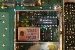
Realistic Pro 2006 10MHz xtal oscillator.JPG
 
Last edited:

fineshot1

Member
Joined
Sep 17, 2004
Messages
2,532
Location
NJ USA (Republic of NJ)
You could pick off the 10Mhz xtal oscillator output at IC2 Pin 2 and Pin 15 is Gnd. I would use a
small coax(like RG-174) routed to the rear panel with either a mounted BNC or RCA jack.
 

videobruce

Member
Premium Subscriber
Joined
Jan 5, 2004
Messages
400
Location
Buffalo NY
Ok, I found the text, (but I didn't include the source when I C&P'ed), but I believe it was from Bill Cheek;

USE YOUR PR0-2004/6 AS A PRECISION FREQUENCY STANDARD

Identify X-301 and the 16-pin MC145158 chip.
Then locate Pin 14 of the chip, which is the source for
the 10 MHz output of X-301 .

Trim all but about 1/8" of the leads of a 0.01-uF disk capacitor and solder one of the leads to Pin 14 of the MC145158 chip. To the other leg of the cap, solder the center conductor of a section of mini coax cable such as RG-177/U. Solder the shield of this coax to the sidewall of the metal compartment that houses X-301 and the chip. Route the coax to the rear of the scanner’s chassis and install a BNC jack. Now trim a notch or hole in the cover of X-301 ’s metal shield compartment so the cover can fit back on over the coax.

EPILOGUE: I have evaluated X-301 in every PR0-2004/5/6 that has crossed my bench since 1986 and in all that time, the worst case of inaccuracy I have noted was about 40 Hz and that unit had problems! The rest have been within 20 Hz and most within 10 Hz. Therefore, even if you have no method or desire to adjust X-301, you can still use the above modification as a standard frequency output for a variety of purposes!
 

videobruce

Member
Premium Subscriber
Joined
Jan 5, 2004
Messages
400
Location
Buffalo NY
I thought there was some component between that pin and the center lead of the coax. (I used RG174 with my original unit).
 

cmdrwill

Member
Joined
Mar 30, 2005
Messages
3,984
Location
So Cali
I would have a coupling capacitor and maybe a series resistor so the IC's 10 mhz does not get loaded down.
 

Ubbe

Member
Joined
Sep 8, 2006
Messages
9,033
Location
Stockholm, Sweden
What can that 10MHz signal be used for? I would think that a 30 year old scanner might not give an accurate enough and stable signal to be used for any serious applications. Many GPS units can supply a 10MHz reference that are extremely accurate that can be used to calibrate frequency counters.

/Ubbe
 

RFI-EMI-GUY

Member
Joined
Dec 22, 2013
Messages
6,871
It looks like the TCXO in that old radio has an adjustment screw (If only my Uniden BCD536HP had one!). The Bill Cheek (may he RIP), quote implies a a typical, uncorrected 4 ppm stability. Of course that was 34 years ago.

The OP can use WWV and a shortwave radio and zero beat that thing pretty close on by ear. You would want it better than 1 Hz for basic UHF work. But even 10 Hz long term would be 1 PPM.

When I was younger, dumber, poorer and happier, I used the VCO - LO in my Bearcat 210 as a signal generator for tuning UHF radios. All it took was subtracting (or adding?) the IF frequency. I also had one of those Measurements/Boonton lunch box signal generators that had an excellent attenuator and FM modulator but I never knew what frequency it was on, so the Bearcat became my frequency reference.
 
Last edited:

videobruce

Member
Premium Subscriber
Joined
Jan 5, 2004
Messages
400
Location
Buffalo NY
EPILOGUE: I have evaluated X-301 in every PR0-2004/5/6 that has crossed my bench since 1986 and in all that time, the worst case of inaccuracy I have noted was about 40 Hz and that unit had problems! The rest have been within 20 Hz and most within 10 Hz. Therefore, even if you have no method or desire to adjust X-301, you can still use the above modification as a standard frequency output for a variety of purposes!
What would you use the 10MHz for? It would be way off frequency after 20yrs or more and not very stable when it was new.
A frequency standard, better than the counter I already have (Optotronics UTC3000)

BTW, AFA tuning, I don't have a GPS unit, nor a HF receiver. I was aware of zero beating WWV as I did it ago for the unit I modded 30 or so years ago.
 
Status
Not open for further replies.
Top