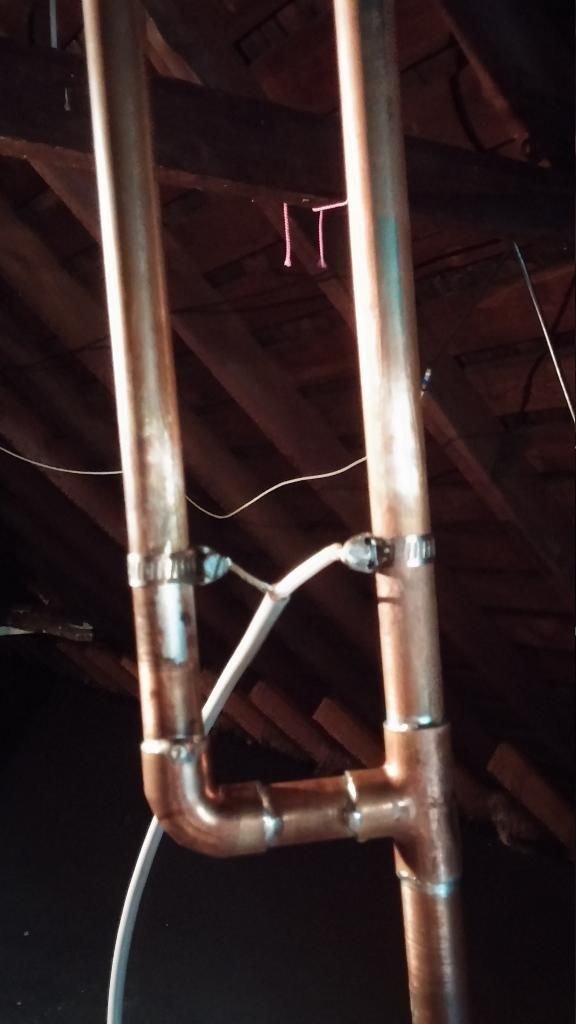
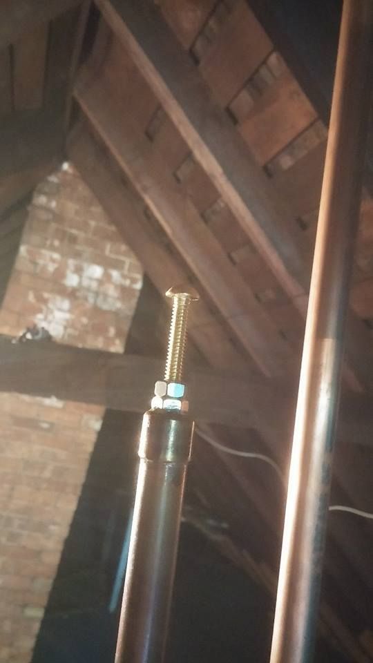
2 Meter J-pole tunning

Status
Not open for further replies.

kd2goe

Member
Joined
Mar 27, 2013
Messages
163
Location
Buffalo
I made a J-Pole antenna but I am having a hell of a time getting the match down on 145mhz right now my swr is 1.2:1 is at the top of the band 148mhz.. the tuning stubs seem to do nothing and I adjusted the feed point all over the place, and this is the best I can get right now.
here is a video if me sweeping through 2 meters and some pics of my J-pole any tips would help...

https://www.youtube.com/watch?v=btRJ03Z3GOg
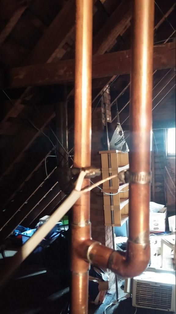


ko6jw_2

Member
Premium Subscriber
Joined
May 18, 2008
Messages
1,469
Location
Santa Ynez, CA
First of all, you have done a very good job with your construction. I have had exactly the same problem. The key is to understand that a J-pole is a balanced load. Feeding it directly from 50 ohm coax will work, but with problems like you are describing. You need to make a coaxial balun from a 1/2 wave length of coax. The feed point may be a bit higher up. Remember to take into account the velocity factor of your coax making the 1/2 wave section shorter than the free space length. Form a U shape with the 1/2 wave section and connect the shields of the U section and your feedline together. Connect the center conductor of the feedline and one of the sides of the balun together and then to one side of the J. Connect the center conductor of the other side of the balun to the other side of the J. Move the feed point up or down to tune. You'll find that it is much flatter across the band. The ARRL antenna book has more information.

You don't need to worry too much about the exact length of the balun section other than taking the velocity factor into account.
 

prcguy

Member
Premium Subscriber
Joined
Jun 30, 2006
Messages
16,645
Location
So Cal - Richardson, TX - Tewksbury, MA
A string of maybe 25, #43 mix ferrite beads on the first 6in of coax should also do the trick or a small #43 toroid and a few turns of coax through it. You might run your hand up and down the coax and see if the match changes, that will usually let you know if there are common mode currents on the coax from an imbalance or high VSWR.

You could also try reversing the coax with the hot on the stub and ground to long element and Ty-rap the coax down the mast for a distance.
prcguy
 

prcguy

Member
Premium Subscriber
Joined
Jun 30, 2006
Messages
16,645
Location
So Cal - Richardson, TX - Tewksbury, MA
What you described is a 4:1 balun, why would you recommend that for an antenna that already has a 1/4 wave matching section and only needs some common mode choking, which ferrite beads will accomplish much easier.

I would forget the J-pole and make a ground plane, its easier and can be repeated from instructions without any tuning. Most people who make J-poles and don't have an antenna analyzer probably have less performance than a ground plane anyway because of the J-pole tuning problems.
prcguy


Forget the beads, just make the balun.
 

ko6jw_2

Member
Premium Subscriber
Joined
May 18, 2008
Messages
1,469
Location
Santa Ynez, CA
I don't invent this stuff. It's in the ARRL antenna book. J-poles are end fed half-waves also known in the old days as Zepp antennas. The are balanced loads. But, never mind. I've built more than a few and I can read antenna theory. A half-wave end-fed antenna is a high impedance balanced load. Hence, the 4:1 balun. Make it anyway you want, but just don't expect it to work as well. A ground plane is a unity gain antenna. A J-pole has about 3dbi gain. That's why we use them.
 

prcguy

Member
Premium Subscriber
Joined
Jun 30, 2006
Messages
16,645
Location
So Cal - Richardson, TX - Tewksbury, MA
Yes a J-pole is a half wave end fed, which is several thousand ohms but it includes a 1/4 matching stub which is the thing that the OP is sliding the coax up and down on to get it matched, which is how they are matched. You would not use a 4:1 balun to match an end fed half wave, it needs a very high ratio like 60:1 or more and that's what a 1/4 wave stub can do.

There would be noting in the ARRL antenna handbook about using a 4:1 coax balun on a J-pole, I even looked in all the editions I have here and can't find it and probably because it would not be correct info. BTW, a J-pole has about 1.5dB more gain than a 1/4 wave ground plane on a good day when made and tuned right, which is very difficult unless you have an antenna analyzer or radio and wattmeter and a lot of patience. That's why ground plane antennas are good, they can be built from plans and they work great without any tuning and they rarely have common mode RF current problems, which is probably what the OP is experiencing.
prcguy

I don't invent this stuff. It's in the ARRL antenna book. J-poles are end fed half-waves also known in the old days as Zepp antennas. The are balanced loads. But, never mind. I've built more than a few and I can read antenna theory. A half-wave end-fed antenna is a high impedance balanced load. Hence, the 4:1 balun. Make it anyway you want, but just don't expect it to work as well. A ground plane is a unity gain antenna. A J-pole has about 3dbi gain. That's why we use them.
 

jaspence

Member
Premium Subscriber
Joined
Mar 21, 2008
Messages
3,041
Location
Michigan
J pole antenna

I have built a few of these successfully, and used both ways with little differences in performance. The easiest way to get a good one is to buy one of the Ed Fong models available from HRO or on ebay.
 

kd2goe

Member
Joined
Mar 27, 2013
Messages
163
Location
Buffalo
ok welI flipped the feed point and I got it down to 1.3:1 at 144.95 so that is good but when I compare it to the 1/4 ground plan. I am giving my friend 2 more s units with the 1/4 wave
 

ko6jw_2

Member
Premium Subscriber
Joined
May 18, 2008
Messages
1,469
Location
Santa Ynez, CA
Yes a J-pole is a half wave end fed, which is several thousand ohms but it includes a 1/4 matching stub which is the thing that the OP is sliding the coax up and down on to get it matched, which is how they are matched. You would not use a 4:1 balun to match an end fed half wave, it needs a very high ratio like 60:1 or more and that's what a 1/4 wave stub can do.

There would be noting in the ARRL antenna handbook about using a 4:1 coax balun on a J-pole, I even looked in all the editions I have here and can't find it and probably because it would not be correct info. BTW, a J-pole has about 1.5dB more gain than a 1/4 wave ground plane on a good day when made and tuned right, which is very difficult unless you have an antenna analyzer or radio and wattmeter and a lot of patience. That's why ground plane antennas are good, they can be built from plans and they work great without any tuning and they rarely have common mode RF current problems, which is probably what the OP is experiencing.
prcguy

I guess your ARRL books don't go back as far as mine. You are clearly an expert. I've only been involved with radio and antennas for 52 years - so what do I know. I am attaching a discussion of j-poles from the 1988 ARRL Antenna Handbook. Read the entire discussion, especially the paragraph which begins with "Fig 35 shows..." You might actually learn something.
 

Attachments

  • j-pole.pdf
    117.2 KB · Views: 301

prcguy

Member
Premium Subscriber
Joined
Jun 30, 2006
Messages
16,645
Location
So Cal - Richardson, TX - Tewksbury, MA
There are things that get into ARRL publications that are not quite right and they get deleted in subsequent publications for a good reason. In my opinion the use of a 4:1 balun on a J-pole is one of them because the 1/4 wave stub can be tapped for just about any impedance from a few ohms to the infinity. The problem with a J-pole is common mode currents on the coax and a 1:1 or choke balun would be more appropriate.
prcguy

Edit: I found the mention of a 4:1 balun still in various editions of the ARRL antenna handbook but under mobile antennas. This contradicts the main J-pole projects in the antenna handbook under VHF/UHF antennas where they are feeding the 1/4 wave stub directly with coax and recommending a common mode choke on the feedline.


I guess your ARRL books don't go back as far as mine. You are clearly an expert. I've only been involved with radio and antennas for 52 years - so what do I know. I am attaching a discussion of j-poles from the 1988 ARRL Antenna Handbook. Read the entire discussion, especially the paragraph which begins with "Fig 35 shows..." You might actually learn something.
 
Last edited:

prcguy

Member
Premium Subscriber
Joined
Jun 30, 2006
Messages
16,645
Location
So Cal - Richardson, TX - Tewksbury, MA
I agree with everything said in Toms link. A J-pole has inherent difficulties with decoupling the feedline and in most cases a 1/4 wave ground plane is much more repeatable to build and will probably work better. However, there should not be much difference between them and something else may be wrong with the OPs J-pole. Were the dimensions specifically for a copper pipe version?
prcguy


Last edited:

kd2goe

Member
Joined
Mar 27, 2013
Messages
163
Location
Buffalo
I agree with everything said in Toms link. A J-pole has inherent difficulties with decoupling the feedline and in most cases a 1/4 wave ground plane is much more repeatable to build and will probably work better. However, there should not be much difference between them and something else may be wrong with the OPs J-pole. Were the dimensions specifically for a copper pipe version?
prcguy


I used plans for a half inch copper pipe jpole. I verified the plans with three other different calculators.
I'll post the specs when i get home
 
Status
Not open for further replies.
Top