• To anyone looking to acquire commercial radio programming software:

    Please do not make requests for copies of radio programming software which is sold (or was sold) by the manufacturer for any monetary value. All requests will be deleted and a forum infraction issued. Making a request such as this is attempting to engage in software piracy and this forum cannot be involved or associated with this activity. The same goes for any private transaction via Private Message. Even if you attempt to engage in this activity in PM's we will still enforce the forum rules. Your PM's are not private and the administration has the right to read them if there's a hint to criminal activity.

    If you are having trouble legally obtaining software please state so. We do not want any hurt feelings when your vague post is mistaken for a free request. It is YOUR responsibility to properly word your request.

    To obtain Motorola software see the Sticky in the Motorola forum.

    The various other vendors often permit their dealers to sell the software online (i.e., Kenwood). Please use Google or some other search engine to find a dealer that sells the software. Typically each series or individual radio requires its own software package. Often the Kenwood software is less than $100 so don't be a cheapskate; just purchase it.

    For M/A Com/Harris/GE, etc: there are two software packages that program all current and past radios. One package is for conventional programming and the other for trunked programming. The trunked package is in upwards of $2,500. The conventional package is more reasonable though is still several hundred dollars. The benefit is you do not need multiple versions for each radio (unlike Motorola).

    This is a large and very visible forum. We cannot jeopardize the ability to provide the RadioReference services by allowing this activity to occur. Please respect this.

Advice for latest car rewire

Status
Not open for further replies.

PrivatelyJeff

Has more money than sense
Premium Subscriber
Joined
Jun 5, 2016
Messages
1,056
Location
Kings County, CA
CAR WIRING.jpg

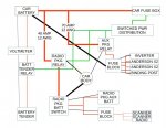
I'm about to rewire my car (2011 Ford Fiesta) and I was hoping to get some advice and ideas from some of the experts here. I'm including a diagram for reference.

Because of my after market alarm and remote start kit, I have a parasitic drain on the battery that discharges the battery after sitting a few days, so I am hard wiring a circuit for a 2 amp battery tender. It will go through a relay set to cut it off from the battery when the engine starts. On the other side of the relay, it will connect to a voltmeter (with power switch) and the car battery.

Off the car battery, on the positive side I have two fuse-able link studs. One is 40 amp and the other is 70 amp (they will be fused to 35 and 60 amps) and will be either 10 or 12 AWG wiring. They will both be wired inside the cab to relays which will be ignition triggered by a unused 20 amp ignition triggered circuit. The 20 amp circuit will feed a small fuse block, which will then feed lines to the battery tender cutoff relay, both lines off the battery and eventually a dash cam. I am choosing to install the relays as I have left equipment on in the past and have drained the battery and want to eliminate that from happening again.

Off of the 70 amp circuit, after the relay, it will feed to a fuse block with ground, which will feed to a 400 watt inverter, and a mix of anderson power poles, standard automotive accessory outlets and also a binding post. This circuits and sub circuits will ground back to the fuse block and ultimately directly to the car battery, due to the inverter requiring it. There is no monitoring circuitry for the ground side of the car.

Off of the 40 amp circuit, after the relay, it will feed a
West Mountain Radio ISOpwr+ (Plus) Auxiliary Battery Isolator, which will feed a fuse block that will then feed a Anytone AT-D578UV dual band radio (max 15 amp), two scanners (2 amps), a multicoupler (less than an amp) and any other future radio. The battery isolator will have attached to it a small, sealed lead-acid battery of 7-20 amp hours, designed to power the RF systems temporarily while the car is off. At this time, there is no plans for sustained operations in the vehicle while the engine is off. I'm installing the isolator after the cutoff relay, as it will allow me to add none battery powered equipment to the circuit in the future if needed. The circuit will be grounded to the car frame.

What do you think?
 

mmckenna

I ♥ Ø
Joined
Jul 27, 2005
Messages
23,881
Location
Roaming the Intermountain West
Off the car battery, on the positive side I have two fuse-able link studs. One is 40 amp and the other is 70 amp (they will be fused to 35 and 60 amps) and will be either 10 or 12 AWG wiring.

You need a larger size conductor to be pulling that much power.

For the 60 amp fused circuit, you should be using 6 AWG to overcome voltage drop and wire heating.
For the 35 amp fused circuit, you are probably going to have trouble finding a 35 amp fuse. You'll need to use a 40 amp fuse. That's going to mean 8 gauge or larger wire.

They will both be wired inside the cab to relays which will be ignition triggered by a unused 20 amp ignition triggered circuit. The 20 amp circuit will feed a small fuse block, which will then feed lines to the battery tender cutoff relay, both lines off the battery and eventually a dash cam. I am choosing to install the relays as I have left equipment on in the past and have drained the battery and want to eliminate that from happening again.

Make sure the relays are rated for the amperage you intend to pull through them, and make sure they are rated for continuous duty.

Off of the 70 amp circuit, after the relay, it will feed to a fuse block with ground, which will feed to a 400 watt inverter, and a mix of anderson power poles, standard automotive accessory outlets and also a binding post. This circuits and sub circuits will ground back to the fuse block and ultimately directly to the car battery, due to the inverter requiring it. There is no monitoring circuitry for the ground side of the car.

Off of the 40 amp circuit, after the relay, it will feed a West Mountain Radio ISOpwr+ (Plus) Auxiliary Battery Isolator , which will feed a fuse block that will then feed a Anytone AT-D578UV dual band radio (max 15 amp), two scanners (2 amps), a multicoupler (less than an amp) and any other future radio. The battery isolator will have attached to it a small, sealed lead-acid battery of 7-20 amp hours, designed to power the RF systems temporarily while the car is off. At this time, there is no plans for sustained operations in the vehicle while the engine is off. I'm installing the isolator after the cutoff relay, as it will allow me to add none battery powered equipment to the circuit in the future if needed. The circuit will be grounded to the car frame.

What do you think?

Sounds overly complex, but I get what you are trying to do. If this was a larger vehicle, I'd say just add a second battery with an isolator. But finding a place to stick a full size battery is going to be difficult.

What is your reasoning behind having the battery maintainer isolated with a relay?
 

mmckenna

I ♥ Ø
Joined
Jul 27, 2005
Messages
23,881
Location
Roaming the Intermountain West
I'm looking at this some more.

I think you have over built this by quite a bit. I'm unsure how you'd draw enough power to need a 70 amp and a 35 amp circuit. I think you could combine this into one circuit off the battery and make life a lot easier. One continuous duty rated solenoid off the battery to feed everything you are adding would simplify the wiring. Control that solenoid off your ignition circuit. Fuse the circuit for 80 amps and use 4 awg wire to a distribution point.

As for the inverter:
I'm running a Samlex 300 watt pure seine wave inverter in my work truck and It's on a 60 amp circuit breaker fed with 6 AWG wire. Never had any issues with it. It shipped from the vendor with 10 gauge wire, so they felt that was large enough. It draws no where near 60 amps. I simply ran a 60 amp circuit to the service body to support the inverter, some ciggy lighter outlets an a radio battery charger. I added a small 12 volt solar panel on the top of one of the bins to overcome the minimal parasitic draw of the radios in the cab (fed off a separate 60 amp circuit).
 

RFI-EMI-GUY

Member
Joined
Dec 22, 2013
Messages
6,877
I would ditch the aftermarket alarm system if it is putting that much parasitic drain on the system. Find a different alternative.

I have a Ford Expedition and had high parasitic drain. It was a ***** to sort out.

1) My rear windshield wiper motor was frozen, thus very high parasitic drain.
2) The Body Control Module must time out 45-60 minutes before all the CPU's tied to it shut down. Then you will have a fairly tiny drain. If your alarm system is keeping it awake, there's your problem.
3) At the end of all this my new battery (in warranty) was tired and needed replacement anyway.
 

RFI-EMI-GUY

Member
Joined
Dec 22, 2013
Messages
6,877
4) Your inverter and Anderson/Binding posts should return to body ground not directly to A - battery terminal
 

mmckenna

I ♥ Ø
Joined
Jul 27, 2005
Messages
23,881
Location
Roaming the Intermountain West
I'll add this,
The 300 watt inverter I have is on a separate disconnect switch. I keep it completely powered off when not in use. While the inverter has it's own power switch on it, I didn't trust it, wanted to make sure I was a zero consumption on that.

And the small solar panel helped out a lot. I've left the truck sitting for 3 weeks at a time and no issues.
 

PrivatelyJeff

Has more money than sense
Premium Subscriber
Joined
Jun 5, 2016
Messages
1,056
Location
Kings County, CA
Would I need to bump it up even with a short run? The max run for the 60 amp circuit will be less than 5 feet and the 40 amp will be less than 7. I’m also over building now because I’ve found that when I went with smaller circuits in the past, I would eventually outgrow them and have to upgrade again. This is the 3rd time upgrading the auxiliary circuit so now I’m just going to max the feed lines out and just be done with that for now. I also can’t do 80 amps off the battery as I have no physical way of connecting to the battery besides these two studs

I’ll keep that in mind for the relays. I was looking at some ones designed for racing cars that have up high amps and also for headlights.

As for the tender, so if I leave it plugged in and remote start the car, that there isn’t too much voltage going into the system. It’s not something that will happen often but I’d rather not risk it. In the winter months, I often leave for work at 6 and it can be bitterly cold and also have very thin ice on the windows.

I would LOVE to either upgrade the battery or install a second one but it being a small car, it’s impossible. The battery it comes with is just big enough for it.

all this is to have everything I want and also not have a dead battery when I go to leave for work or go home.
 

PrivatelyJeff

Has more money than sense
Premium Subscriber
Joined
Jun 5, 2016
Messages
1,056
Location
Kings County, CA
I would ditch the aftermarket alarm system if it is putting that much parasitic drain on the system. Find a different alternative.

Not after as much as I paid for it and it’s not a high drain. The battery is tiny and it takes about 4-5 days to take it down to less than 11 volts. It wasn’t a problem until the pandemic started and I suddenly had nowhere to go for days.
 

PrivatelyJeff

Has more money than sense
Premium Subscriber
Joined
Jun 5, 2016
Messages
1,056
Location
Kings County, CA
4) Your inverter and Anderson/Binding posts should return to body ground not directly to A - battery terminal

Every inverter install I’ve seen and read about requires it to be tied to the battery ground. The others are too, but only because all this equipment is mounted to a center console kick plate that has to be removed to service the HVAC filter, and is linked to the car by a large gauge quick disconnect cable.
 

RFI-EMI-GUY

Member
Joined
Dec 22, 2013
Messages
6,877
Every inverter install I’ve seen and read about requires it to be tied to the battery ground. The others are too, but only because all this equipment is mounted to a center console kick plate that has to be removed to service the HVAC filter, and is linked to the car by a large gauge quick disconnect cable.

The 12V Anderson and Binding post should normally go to body as there are potential voltage differential problems.

As far as the inverter, some perhaps most of the bargain ones are a modified sine wave without transformer isolation and the grounding terminal on the AC outlet simply floats. (No connection inside)

For example we are used to neutral being at or near "earth-ground" potential, it wont be, the neutral terminal will swing at 1/2 115 VAC and the hot terminal will do the opposite phase. It normally is not a problem, but if you are powering sensitive instrumentation it might be. You certainly don't want to correct it. I was surprised to learn this despite it not posing a problem. Just something to consider if you are extending AC power to the rear deck.
 

RFI-EMI-GUY

Member
Joined
Dec 22, 2013
Messages
6,877
Not after as much as I paid for it and it’s not a high drain. The battery is tiny and it takes about 4-5 days to take it down to less than 11 volts. It wasn’t a problem until the pandemic started and I suddenly had nowhere to go for days.

My late Dad had a Porsche Boxster which I was tasked to sort out the electricals before selling it. The remote access / alarm system had a mode it would go into after so many days of inactivity. The alarm functions would still work, but you had to use the drivers side door key instead of the fob to get in and that would wake up the entire system for the next cycle.
 

PrivatelyJeff

Has more money than sense
Premium Subscriber
Joined
Jun 5, 2016
Messages
1,056
Location
Kings County, CA
The 12V Anderson and Binding post should normally go to body as there are potential voltage differential problems.

As far as the inverter, some perhaps most of the bargain ones are a modified sine wave without transformer isolation and the grounding terminal on the AC outlet simply floats. (No connection inside)

For example we are used to neutral being at or near "earth-ground" potential, it wont be, the neutral terminal will swing at 1/2 115 VAC and the hot terminal will do the opposite phase. It normally is not a problem, but if you are powering sensitive instrumentation it might be. You certainly don't want to correct it. I was surprised to learn this despite it not posing a problem. Just something to consider if you are extending AC power to the rear deck.

I’ll keep that in mind. I would normally do that but just the way but the way everything is mounted, there isn’t a any bolts that are grounded until you get WAY up under the dash, and it’s virtually impossible for me to reach that bolt. The car is designed to be very light weight so most of everything is plastic inside the cab.
 

PrivatelyJeff

Has more money than sense
Premium Subscriber
Joined
Jun 5, 2016
Messages
1,056
Location
Kings County, CA
My late Dad had a Porsche Boxster which I was tasked to sort out the electricals before selling it. The remote access / alarm system had a mode it would go into after so many days of inactivity. The alarm functions would still work, but you had to use the drivers side door key instead of the fob to get in and that would wake up the entire system for the next cycle.

Interesting. I don’t think mine has that. Probably what I get for going with the cheaper option.
 

RFI-EMI-GUY

Member
Joined
Dec 22, 2013
Messages
6,877
Interesting. I don’t think mine has that. Probably what I get for going with the cheaper option.

That Boxster in my opinion was a poorly engineered vehicle. They tried to make it do way too much and engineered themselves into so many corners, requiring some other genius engineering trick to bail them out.

It is not a vehicle you want to encounter a stone dead battery in the dead of winter as the battery is ELECTRICALLY LOCKED/UNLOCKED , inside the front trunk (FRUNK).
 

PrivatelyJeff

Has more money than sense
Premium Subscriber
Joined
Jun 5, 2016
Messages
1,056
Location
Kings County, CA
That Boxster in my opinion was a poorly engineered vehicle. They tried to make it do way too much and engineered themselves into so many corners, requiring some other genius engineering trick to bail them out.

It is not a vehicle you want to encounter a stone dead battery in the dead of winter as the battery is ELECTRICALLY LOCKED/UNLOCKED , inside the front trunk (FRUNK).

That reminds me of a time when girlfriends car battery was dead. She had the jumper cables for it, but they were in the trunk, that only uses an electronic release, and the seats could only fold down if you pulled the release for them in the trunk. I had some cables that were too short so I had to drive up on the lawn of her apartment complex to get close enough to hook up and get her started.
 

mmckenna

I ♥ Ø
Joined
Jul 27, 2005
Messages
23,881
Location
Roaming the Intermountain West
Would I need to bump it up even with a short run? The max run for the 60 amp circuit will be less than 5 feet and the 40 amp will be less than 7.

6awg would be the smallest I'd run. In a pristine environment, no more than 30ºc with the wire in free space and using a conductor with 90ºc rated insulation, 40 amps is the maximum for 12 gauge. Running lower temp insulation and in a car drops that down to 25 amps maximum.

For safety sake, you really, really need to be running 6 gauge. A failure will result in a fire. Too small a conductor and you'll see significant voltage drop. That voltage drop gets lost as heat in the conductor. The voltage drop will impact radio performance. Trying to save a few bucks on wire is going to create more headaches than it's worth.


I also can’t do 80 amps off the battery as I have no physical way of connecting to the battery besides these two studs

There's a number of ways to attach directly to the battery. I'd not let that limit you. You are putting a lot of planning and thought into this. Might as well take it the rest of the way.


As for the tender, so if I leave it plugged in and remote start the car, that there isn’t too much voltage going into the system.

Won't hurt it.

all this is to have everything I want and also not have a dead battery when I go to leave for work or go home.

A master kill switch or solenoid, like you are planning on doing, should take care of that.

However, if you are drawing a lot of power off the system while you are driving, you may exceed the capacity of the alternator to keep up. I'd start searching around and figure out what the rating is on the alternator you have. Understand that the rating will be for the engine running at a certain RPM. Anything below that RPM will result in less current from the alternator. If you are going to be drawing more than the alternator puts out (running the inverter, radios, not to mention the normal vehicle loads, like heater, headlights, etc, etc, etc) it'll not be able to keep the battery charged. Even with the solenoids disconnecting things, the battery might get overtaxed. Situations like this might require a larger alternator, or as you were planning, adding a charger to keep up. But that's getting risky. If the power goes out and you cannot keep the battery charged, you'll have issues.
 

PrivatelyJeff

Has more money than sense
Premium Subscriber
Joined
Jun 5, 2016
Messages
1,056
Location
Kings County, CA
The only terminals available on the positive terminal are the ones rated for 70 and 40 amps. The others are maxed out already with the built in car lines and the alarm/remote start. The studs also only have so much space to connect things and the connections need to have a 10 mm hole.

I guess I could have been more clear, I’m trying to max out the power at the feed point. Whatever I get at the end will just have to be whatever I get. I ran a 10 gauge wire for the radio system a year ago and it’s been fine so far with negligible voltage drop at the end. I went with full copper, high temperature rated wire that’s loomed from end to end and routed away from anything that generates heat. I’m only considering replacing it because I was rushed and didn’t use water proof connectors.

as for the alternator, it’s 82 amps at idle and 120 at high RPM in its stock form. I’m not planning on running everything at full power all the time so if the radios have to go off to run the inverter at full power, then so be it and visa-versa. I try to run everything at 5v or 12v anyway so it won’t be used much. Same with the radios. It’s just having the ability of need be is nice to have. I’m also hard wiring in a voltmeter that’s connected in line with the charger so I can always monitor the battery. If worse comes to worse, upgrading the alternator is easy to do.
 

phask

Member
Premium Subscriber
Joined
Dec 19, 2002
Messages
3,684
Location
KZZV - SE Ohio
That Boxster in my opinion was a poorly engineered vehicle. They tried to make it do way too much and engineered themselves into so many corners, requiring some other genius engineering trick to bail them out.

It is not a vehicle you want to encounter a stone dead battery in the dead of winter as the battery is ELECTRICALLY LOCKED/UNLOCKED , inside the front trunk (FRUNK).

Actually, there is a way, just Google it.
 
Status
Not open for further replies.
Top