AR8600-MK2 Advice wanted with Programming Cable for AOR 8600 Mk2

Status
Not open for further replies.

AOR-262

Member
Joined
May 10, 2016
Messages
308
I've got a USB-Serial programming cable that I use with my 8600, identical to the one here ...

USB COM Cat control cable for AOR AR-2500 AR-3030 AR-5000 AR-7000 AR-8600 | eBay

What my intention is, I'm going to make my own programming cable for the AOR 8000 and wondered if anyone knows the individual names of each of all of the pins on the 9-Pin Serial end. In particular, I only need to know which pins will give me +5v, Tx and Rx.

TIA
 

dkf435

Member
Joined
Apr 15, 2006
Messages
735
Location
Sweet Home/Foster OR
Until I put a new case on the AR8000 I had 2 3.5mm stereo plugs, one was RX/TX/GND and the other was SQ/RXAudio/GND. If you can get some of the right pitch flex cable there is an OPTOLINX universal TTL to RS232 level converter on Ebay right now.

There is no +5v on the RS232, some programs will hold the DTR or CSR high to power the interface through the corresponding pin, but +5v is available on the AR8000 FFC connector.

Had the EEB, AOR Japan and AOR USA cables and both the Optoelectronics CX12AR and Optolinx for the AR8K and liked the Optoinx the most as it had a stable independent power supply and you could make cables to fit anything

David
 

AOR-262

Member
Joined
May 10, 2016
Messages
308
@dkf435

Thanks for your reply. However, I think you've answered differently to what I was expecting.

If you click on the link in my original post, that is a programming cable for the AOR 8600 Mk2 (which I already have). The end connector is a 9-Pin DB9 connector. I don't believe every one of the 9-Pins are used; I guess maybe only 3 or 4 are used -- to transmit/receive data. If I had a schematic diagram of that cable, I could work out what Pins can be used. Take a look at this item ...

https://uk.farnell.com/ftdi/ttl-232rg-vsw5v-we/cable-ttl-usb-conv-wire-end-5v/dp/2352003#

If you look at the Technical Data of the item; click link below ...

http://www.farnell.com/datasheets/1...1.1617272641.1562669141-2022219839.1562669141

There are 6 wires on that item, only 3 wires I need ... +5v, Tx and Rx.

On the Motherboard of the AR8000 the three Pins I need to use are +5v, Tx and Rx -- would you know if the +5v on the board is already +5v or does it require +5v?
 

dkf435

Member
Joined
Apr 15, 2006
Messages
735
Location
Sweet Home/Foster OR
On the cable made for the 8200 between the 8200 connector and the DB9 there is a level converter that goes from TTL+5 to RS232 with +- voltages. You either need a MAX232 chip or a transistor circuit for that in a DB9 to FFC AR8000 cable. The FFC connector on the 8000 has Tx,Rx, gnd +5, unfiltered audio, squelch and not sure what else I leftout, need to dig out service manual to get exact pinout. The easiest eay to do the interface for the 8000 to startout is look up the Scout mod to connect to the 8000 and use a 3.5mm stereo jack instead and add one more wire and solder to pads on TX RX and signal GND on FFC connector header, the USB interface does not need the +5 it gets powered from computer. Then get the FTDI cable and solder on the 3.5mm stereo plug and that will bypass the need for the FFC.
 

AOR-262

Member
Joined
May 10, 2016
Messages
308
@dkf435

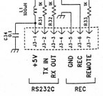
Here is a schematic snapshot of the RS232 circuitry of the AOR 8000 ...

Image-1.jpg


This is the schematic wiring for the USB Cable ... (note: Wire 1 (VCC) is +5v)

Image-2.jpg

This is the cable I intend to buy (see link below). [once the USB is plugged in and the drivers are installed it will be recognized as a Virtual COM device (it uses a FTDI FT232R Chip, Windows 10 compatible); thus becoming a generic converter cable providing a TTL Serial interface with various logic levels.

https://uk.farnell.com/ftdi/ttl-232rg-vsw5v-we/cable-ttl-usb-conv-wire-end-5v/dp/2352003#


Going back to the AOR 8000 schematic diagram, I only need to use +5v, Tx and Rx. Looking at the cable wiring description -- question is: would I only need to use VCC (+5v), TXD and RXD.

Secondly, the +5v on the AOR 8000, does that mean I need to supply +5v or the circuitry of the AOR will already give me +5v
 

dkf435

Member
Joined
Apr 15, 2006
Messages
735
Location
Sweet Home/Foster OR
If the USB converter is powered from computer it should not connect to the +5v output on the AR8000 radio. The +5 output on the radio was for the recorder control cable and the CU232 interface that did the cloning and computer programming of the AR8000 radios. Since the CU232was not allowed in to the US because of the cloning could remove the cell blocks EDCO the AOR company for the USA made an interface that was contained within a RS232 DB25 shell and used the +5 because it was more reliable then being powered of a RS232 port as not all ports coulsd supply power for the interface..

TXD RXD and GND need to be connected to the radio for communication. Do the AR8000 Scout reaction tune mod where you install a 3 conductor 3.5mm jack in the side of the radio, if you cannot find any FFC cables. I used some old wirewrap wire to do the connections, thin insulation and flexible and just tackk soldered them to the traces next to the FFC connector.
 

AOR-262

Member
Joined
May 10, 2016
Messages
308
@dkf435

Thanks very much. Your advice has been great. You were spot-on with the use of the +5v. Do not use it! Here's a copy of a reply from AOR I received earlier:

___

Dear Sir,

Thank you for using AOR receivers.

+5V is coming out from the receiver, therefore do not apply external voltage to it.
In theory you only need 2 wires, TXD and RXD, however we cannot know if your particular setup will indeed function.

Regards,

AOR, Ltd.
www.aorja.com


___

So there we have it. Looks like as you said, it's only the Tx and Rx I need -- maybe the use of GND is not needed, though can't see a problem connecting the GND?
 

dkf435

Member
Joined
Apr 15, 2006
Messages
735
Location
Sweet Home/Foster OR
Not sure how you can just use txd and rxd without a return path. Every interface and reaction tune cable has gnd connected. Not sure but the one unmarked pin J3-4 on the FFC may be the second gnd
 

AOR-262

Member
Joined
May 10, 2016
Messages
308
@dkf435

I think the reply from AOR presumed I know to use GND. I would say from the schematic diagram it would be J3-5 as that is marked as GND -- although J3-4 and J3-5 seem to be linked. The physical layout/design of the PCB doesn't reflect the schematic diagram as you can see in the picture below. (one way to test it would be to use a multi-meter and check for continuity).


Cable.jpg
 

AOR-262

Member
Joined
May 10, 2016
Messages
308
@dkf435

Update:

I have made my own cable utilizing the Tx, Rx and Gnd pins and using Windows HyperTerminal to send commands to the 8000.

The problem I’m having is the HyperTerminal program does not echo back a response from the receiver. The word “REMOTE” flashes on the screen of the 8000 indicating it acknowledges a remote connection. As a way of a simple test, I put the receiver is in VFO mode and then send the command “AT1” which switches on the Attenuator, that works ok – and if I send the command “AT0” it switches off the Attenuator. Other commands I send seem to work ok but have not extensively used/tested them. What I cannot get is a response from the 8000 when I send a command. If I send the command “AT” the receiver should reply back with either “AT0” (Attenuator off) or “AT1” (Attenuator on) but it doesn’t and it doesn’t reply back to any command I send.

I have checked all settings such as Baud Rate, Stop Bits, Parity etc. and everything matches what is mentioned in the CU8232 User Manual.

Seems the 8000 is receiving and executing commands sent to it but not sending the outcome back.

Another example:

If I type “DD” (Report the current VFO data), the response echoed back from the receiver should be:

RF0001134000_ST009000_AU1_MD2_AT0

But I get nothing?

Any ideas why?
 
Status
Not open for further replies.
Top